SLLA642 July 2024 TUSB564-Q1
4 USB 9-Meter System
To simulate a long cable USB system, two 4.5-meter USB-C cables are used in the signal path. One cable is placed before the TUSB564-Q1, and the second cable is placed after the TUSB564-Q1. The bench board adds additional loss with it's short pre and post-channel FR4 trace. A USB-C host is connected upstream, and measurements are taken at the end of the downstream USB cable.
 Figure 4-1 USB 9-Meter System Block
Diagram
Figure 4-1 USB 9-Meter System Block
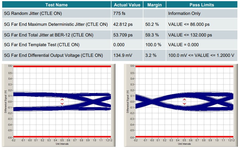
DiagramFor this test, the equalization setting used on the TUSB564-Q1 is setting #9. This adds 7.0dB of gain on the downstream facing port. Figure 3-2 shows the results of a 5G far end USB compliance test taken at the downstream end of this system.
 Figure 4-2 USB 9-Meter System Test
Results
Figure 4-2 USB 9-Meter System Test
ResultsOnce again, the 5G USB compliance test is able to pass in this configuration with no issues. The equalization from the TUSB564-Q1 is countering the added insertion loss from two 4.5-meter cables. This allows the eye to keep a defined shape as shown in the diagrams above. One thing to note is that there is a decrease in the differential output voltage between this test and the 4-meter system test. This is expected, as the TUSB564-Q1 is a linear re-driver which cannot alter the output swing of a signal. Tuning the output swing of the host can help to counter this if the application is expected to be long channel.