SLLA642 July 2024 TUSB564-Q1
3 USB 4-Meter System
As a starting point for testing, two 2 meter USB-C cables are used in the signal path. One cable is placed before the TUSB564-Q1, and the second cable is placed after the TUSB564-Q1. The bench board adds additional loss with the short pre and post-channel FR4 trace. A USB-C host is connected upstream, and measurements are taken at the end of the downstream USB cable.
 Figure 3-1 USB 4-Meter System Block
Diagram
Figure 3-1 USB 4-Meter System Block
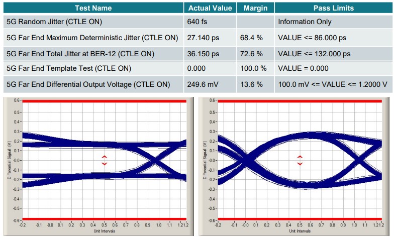
DiagramFor this test, the equalization setting used on the TUSB564-Q1 is setting #3. This adds 2.2dB of gain on the downstream facing port. Figure 3-2 shows the results of a 5G far end USB compliance test taken at the downstream end of this system.
 Figure 3-2 USB 4-Meter System Test
Results
Figure 3-2 USB 4-Meter System Test
ResultsThe 5G USB compliance test is able to pass with no issues in this configuration. The eye diagram shows a defined eye opening and transition area.