SLLSFF7A may 2021 – december 2021 ISOW1044
PRODUCTION DATA
- 1
- 1 Features
- 2 Applications
- 3 Description
- 4 Revision History
- 5 Description Continued
- 6 Device Comparison Table
- 7 Pin Configuration and Functions
-
8 Specifications
- 8.1 Absolute Maximum Ratings
- 8.2 ESD Ratings
- 8.3 Recommended Operating Conditions
- 8.4 ThermalInformation
- 8.5 Power Ratings
- 8.6 Insulation Specifications
- 8.7 Safety-Related Certifications
- 8.8 Safety Limiting Values
- 8.9 Electrical Characteristics
- 8.10 Supply Current Characteristics
- 8.11 Switching Characteristics
- 8.12 Insulation Characteristics Curves
- 8.13 Typical Characteristics
- 9 Parameter Measurement Information
- 10Detailed Description
- 11Application and Implementation
- 12Power Supply Recommendations
- 13Layout
- 14Device and Documentation Support
- 15Mechanical, Packaging, and Orderable Information
3 Description
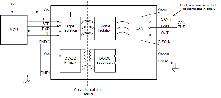
The ISOW1044 device is a galvanically-isolated controller area network (CAN) transceiver with a built-in isolated DC-DC converter that eliminates the need for a separate isolated power supply in space-constrained isolated designs. The low-emissions, isolated DC-DC meets CISPR 32 radiated emissions Class B standard with just two ferrite beads on a simple two-layer PCB. Additional 20 mA output current can be used to power other circuits on the board. An integrated 10 Mbps GPIO channel is available and can help remove an additional digital isolator or optocoupler for diagnotstics, LED indication or supply monitoring.
| FEATURE | ISOW1044 | ISOW1044B |
|---|---|---|
| Protection Level | Reinforced | Basic |
| Surge Test Voltage | 10 kVPK | 7.8 kVPK |
| Isolation Rating | 5000 VRMS | 5000 VRMS |
| Working Voltage | 1000 VRMS/1500 VPK | 1000 VRMS/1500 VPK |
| Package | DFM (20) | DFM (20) |
| Body Size (Nom) | 12.83mm × 7.5 mm | 12.83mm × 7.5 mm |
 Simplified Schematic