SLLU091A January 2006 – September 2022 ISO721 , ISO721M
3 Functional Configuration of the ISO721 and ISO721M
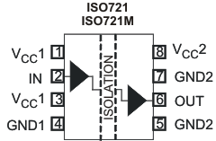
The EVM is configured for the pinout displayed in Figure 3-1. The additional I/Os on the EVM are provided for future development.
 Figure 3-1 The ISO721 and ISO721M Pinout
The ISO721 has TTL input thresholds and a input noise filter that prevents transient pulses of up to 2 ns in duration from being passed to the output of the device.
The ISO721M has a CMOS VCC/2 input threshold and does not have the noise filter and the additional propagation delay. These features of the ISO721M also provide for a 0-Mbps to 150-Mbps signaling rate rather than the ISO721’s 0-Mbps to 100-Mbps signaling rate.