TUSB1046 USB Type-C™ Enabler EVM
TUSB1146 USB Type-C™ Enabler EVM
The TUSB1146 USB Type-C™ Alternate Mode re-driving switch supports data rates up to 10 Gbps for a downstream facing port (host). This user's guide describes how to use the EVM and includes schematics that can be used as a reference design for the alternate mode implementations of the host system with the TUSB1146 device.
Trademarks
USB Type-C is a registered trademark of USB Implementers Forum, Inc.
All other trademarks are the property of their respective owners.
1 TUSB1146EVM-SRC
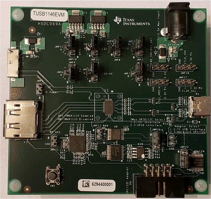
Figure 1 illustrated the EVM board.
 Figure 1. TUSB1146EVM
 The TUSB1146EVM can be used with a legacy DP Source or USB Host system to evaluate the USB Type-C implementation. Figure 2 is a typical test setup
 Figure 2. Test Board Setup
 The EVM comes with a Micro B USB receptacle to connect to USB host systems and a DisplayPort receptacle to connect to DisplayPort-capable source. The TUSB1146 EVM uses the Texas Instruments TPS65987D controller for power delivery and CC pin control.
2 TUSB1146EVM Configuration
This section provides the configuration options available in the TUSB1146EVM.
2.1 TUSB1146 EVM Default EQ Configuration
The headers in Table 1 are provided for TUSB1146 EQ configuration, by default the TUSB1146 EQ settings are configured via I2C controlled by the TPS65987D. Alternatively, the TUSB1146 can be configured using the TI SigCon Architect GUI using the TI USB2ANY or Aardvark I2C adapter connected to connector P4.
Table 1. TUSB1146 Configuration Pins
| Reference Designator | JMP Control | Configuration |
|---|---|---|
| JMP4 | I2C_EN | Install on pins 1-2 |
| JMP13 | SSEQ0/A0 | Install on pins 2-3 |
| JMP10 | DPEQ0/A1 | Install on pins 2-3 |
| JMP22 | I2C Adapter Select | Install on pins 2-3 |
| JMP24 | Mux I2C/GPIO Select | Install on pins 1-2 |
| JMP5 | EQ1 | Install on pins 2-3 |
| JMP2 | EQ0 | Install on pins 2-3 |
| JMP12 | SSEQ1 | Install on pins 2-3 |
| JMP8 | DPEQ1 | Install on pins 2-3 |
2.2 TUSB1146 EQ Control
Each of the TUSB1146 receiver lanes has individual controls for receiver equalization. Table 2, Table 3, and Table 4 detail the gain values for each available combination for downstream, upstream, and all DisplayPort configurations.
Table 2. Configuration Pin-Level Definitions
| Level | Settings |
|---|---|
| 0 | Option 1: Tie 1 kΩ 5% to GND
Option 2: Tie directly to GND |
| R | Tie 20 kΩ, 5% to GND |
| F | Float (leave pin open) |
| 1 | Option 1: Tie 1 kΩ 5% to VCC
Option 2: Tie directly to VCC |
Table 3. USB 3.1 EQ Settings
| USB3.1 Downstream Facing Ports | USB3.1 Upstream Facing Port | ||||||
|---|---|---|---|---|---|---|---|
| EQ Setting # | EQ1 Pin Level | EQ0 Pin Level | EQ Gain @ 5 GHz (dB) | SSEQ1 Pin Level | SSEQ0 Pin Level | EQ Gain @ 5 GHz (dB) | |
| 0 | 0 | 0 | -1 | 0 | 0 | -0.5 | |
| 1 | 0 | R | 1.3 | 0 | R | 1.7 | |
| 2 | 0 | F | 3 | 0 | F | 3.4 | |
| 3 | 0 | 1 | 4.5 | 0 | 1 | 5 | |
| 4 | R | 0 | 5.5 | R | 0 | 6 | |
| 5 | R | R | 6 | R | R | 7 | |
| 6 | R | F | 7.5 | R | F | 8 | |
| 7 | R | 1 | 8.3 | R | 1 | 8.7 | |
| 8 | F | 0 | 9 | F | 0 | 9.4 | |
| 9 | F | R | 9.5 | F | R | 10 | |
| 10 | F | F | 10 | F | F | 10.6 | |
| 11 | F | 1 | 10.5 | F | 1 | 11 | |
| 12 | 1 | 0 | 11 | 1 | 0 | 11.5 | |
| 13 | 1 | R | 11.3 | 1 | R | 11.9 | |
| 14 | 1 | F | 11.6 | 1 | F | 12.1 | |
| 15 | 1 | 1 | 12 | 1 | 1 | 12.5 | |
Table 4. DisplayPort EQ Settings
| All DisplayPort Lanes | |||
|---|---|---|---|
| EQ Setting # | DPEQ1 Pin Level | DPEQ0 Pin Level | EQ Gain @ 5 GHz (dB) |
| 0 | 0 | 0 | -0.4 |
| 1 | 0 | R | 1.3 |
| 2 | 0 | F | 2.8 |
| 3 | 0 | 1 | 4.1 |
| 4 | R | 0 | 6.1 |
| 5 | R | R | 6.2 |
| 6 | R | F | 7.1 |
| 7 | R | 1 | 7.9 |
| 8 | F | 0 | 8.6 |
| 9 | F | R | 9.2 |
| 10 | F | F | 9.8 |
| 11 | F | 1 | 10.3 |
| 12 | 1 | 0 | 10.7 |
| 13 | 1 | R | 11.2 |
| 14 | 1 | F | 11.5 |
| 15 | 1 | 1 | 12 |