SLLU321 July 2022
- TCAN1043AEVM Evaluation Module User's Guide
- Trademarks
- 1Introduction
- 2Test Setup and Results
- 3EVM Setup and Basic Usage
- 4Schematic and Bill of Materials
1.1 TCAN1043A-Q1 EVM
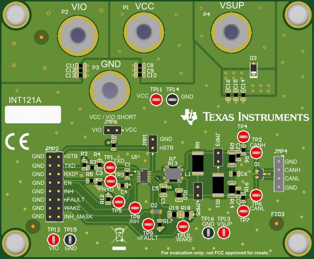
The TCAN1043A-Q1 EVM has simple connections to all necessary pins of the CAN transceiver device, and jumpers where necessary to provide flexibility for device pin and CAN bus configuration. There are test points (loops) for all main points where probing is necessary for evaluation such as GND, VCC, TXD, RXD, CANH, CANL, EN, nFAULT, and WAKE. The EVM supports many options for CAN bus configuration. It is pre-configured with two 120-Ω resistors connected on the bus via jumpers: a single resistor is used with the EVM as a terminated line end (CAN is defined for 120-Ω impedance twisted pair cable) or both resistors in parallel for electrical measurements representing the 60-Ω load the transceiver detects in a properly-terminated network (that is, 120-Ω termination resistors at both ends of the cable). If the application requires split termination, TVS diodes for protection, or a Common Mode (CM) Choke, the EVM has footprints available for this via customer installation of the desired components. Figure 1-1 shows the EVM board image.
 Figure 1-1 TCAN1043A-Q1 Evaluation Module
(EVM)