-
TCAN1462-Q1 Evaluation Module With SIC Network
- Trademarks
- 1Introduction
-
2EVM Setup and Operation
- 2.1
Overview and Basic Operation Settings
- 2.1.1 VCC Power Supply (J2, J3, J9, and TP10)
- 2.1.2 I/O Power Supply VIO (J2, J10, and TP8)
- 2.1.3 Main Supply and I/O Header (J2)
- 2.1.4 TXD Input (J2 or TP6)
- 2.1.5 RXD Output (J2 or TP7)
- 2.1.6 STB or Pin 8 (J1, J2, or TP1)
- 2.1.7 J1 Configuration
- 2.1.8 TP1 Configuration
- 2.1.9 VIO or Pin 5 (J2, J10, or TP8)
- 2.1.10 J10 Configurations
- 2.1.11 J2 Configuration
- 2.1.12 SIC Network Configuration (J7 & J8)
- 2.2 Using CAN Bus Load, Termination, and Protection Configurations
- 2.3 Using Customer Installable I/O Options for Current Limiting, Pullup and Pulldown, Noise Filtering
- 2.1
Overview and Basic Operation Settings
- 3CAN EVM Configuration for TCAN1462-Q1 (Factory Installed)
- IMPORTANT NOTICE
TCAN1462-Q1 Evaluation Module With SIC Network
Trademarks
All trademarks are the property of their respective owners.
1 Introduction
1.1 Overview
TI offers a broad portfolio of high speed (HS) CAN, CAN FD, and CAN SIC transceivers compatible with the ISO11898-2 high speed CAN standards. These include 5-V VCC only, 3.3-V VCC only, 5-V VCC with I/O level shifting and galvanic-isolated CAN transceivers. These CAN transceiver families include product mixes with varying features such as low-power standby modes with and without wake up, silent modes, loop back, and diagnostic modes.
The TI CAN EVM helps designers evaluate the operation and performance of various TI CAN transceivers in normal and SiC networks in accordance with CIA 601-4. It also provides bus termination, bus filtering, and protection concepts. The CAN transceivers are easily configured by the customer for the TCAN1042/51, TCAN1044(A)/57(A), and TCAN1462. Jumper settings, simple soldering tasks, and replacement of standard components are configured as needed. A separate EVM is available for the galvanic-isolated CAN transceiver family.
1.2 CAN EVM
The CAN EVM has simple connections to all necessary pins of the CAN transceiver device, and jumpers where necessary to provide flexibility for device pin and CAN bus configuration. There are test points (loops) for all main points where probing is necessary for evaluation such as GND, VCC, TXD, RXD, CANH, CANL, pin 8 (mode pin), or pin 5 (VIO or NC). The EVM supports many options for CAN bus configuration. It is pre-configured with two 120-Ω resistors that are connected on the bus via jumpers: a single resistor is used with the EVM as a terminated line end (CAN is defined for 120-Ω impedance twisted pair cable) or both resistors in parallel for electrical measurements representing the 60-Ω load the transceiver detects in a properly terminated network (that is, 120-Ω termination resistors at both ends of the cable). If the application requires “split” termination, TVS diodes for protection, or Common Mode (CM) Choke, the EVM has footprints available for this via customer installation of the desired components.
This EVM also has the ability to connect a SiC network, as defined in CIA601-4, to the CAN bus lines via J7 and J8. Connecting the SIC network to CANH and CANL simulates a noisy CAN bus by adding more reflections and ringing to the signals. This can be used to test the reliability of the transceiver in a very noisy environment.
Figure 1-1 shows the EVM board image.
 Figure 1-1 EVM PC
Board
Figure 1-1 EVM PC
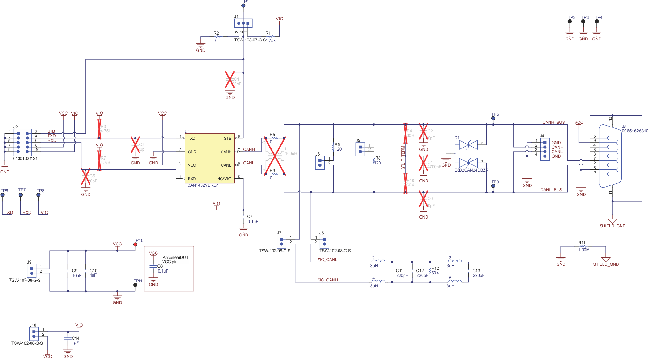
BoardFigure 1-2 shows the EVM schematic.
 Figure 1-2 EVM
Schematic
Figure 1-2 EVM
SchematicTable 1-1 lists the jumper connections for the EVM.
| Connection | Type | Description |
|---|---|---|
| J1 | 3-pin jumper | Used for mode selection on pin 8 (4.7-kΩ pullup to VIO, 0-Ω pulldown to GND, customer-installable pulldown for devices with slew rate control RS pin). |
| J2 | 10-pin header | Connection for access to all critical digital I/O, supply, and GND for driving the CAN transceiver externally with test equipment or interfaced to a processor EVM |
| J3 | 9-pin DB9 connector |
Provides an optional way to connect CANH, CANL, VCC, and GND all through a standard DB9 CAN pinout rather than through a regular header. |
| J4 | 4-pin jumper |
CAN bus connection (CANH, CANL) and GND |
| J5 | 2-pin jumper | Connect 120-Ω CAN termination to the bus. Used separately for a single termination if EVM is at end of the CAN bus and termination is not in the cable. Used in combination with JMP5 to get to second CAN termination to represent the combined 60-Ω load for CAN transceiver parametric measurement. |
| J6 | 2-pin jumper | Connect 120-Ω CAN termination to the bus. Used in combination with JMP4 to get to second CAN termination to represent the combined 60-Ω load for CAN transceiver parametric measurement. |
|
J7 |
2-pin jumper |
Connect SIC network to CANH. Must be used in combination with J8. |
|
J8 |
2-pin jumper |
Connect SIC network to CANL. Must be used in combination with J7. |
|
J9 |
2-pin jumper |
VCC supply and GND connection for the EVM |
|
J10 |
2-pin jumper |
VIO and VCC suuply connection. Provides ability to short Vcc and VIO together. |
| TP1 | Test Point | Device pin 8 test point |
| TP2 | GND test point | |
| TP3 | ||
| TP4 | ||
| TP5 | CANH (bus) test point | |
| TP6 | TXD, Device pin 1 test point | |
| TP7 | RXD, Device pin 4 test point | |
| TP8 | VIO, Device pin 5 test point | |
| TP9 |
CANL (bus) test point |
|
| TP10 |
VCC test point |
|
| TP11 |
GND test point |