SLLU364 may 2023 MCT8315A
- 1
- Abstract
- 1Revision History
- Trademarks
- 2Introduction
- 3Essential Controls
-
4Basic Controls
- 4.1 Device and pin configuration
- 4.2 System level configuration
- 4.3
Control configurations
- 4.3.1 Initial speed detection of the motor for reliable motor resynchronization
- 4.3.2 Unidirectional motor drive detecting backward spin
- 4.3.3 Preventing back spin of rotor during startup
- 4.3.4 Faster startup timing
- 4.3.5 Improving speed regulation
- 4.3.6 Stopping motor quickly
- 4.3.7 Faster deceleration
- 4.3.8 Preventing supply voltage overshoot during motor stop and deceleration
- 4.3.9 Protecting against rotor lock or stall condition
- 4.3.10 Maximizing thermal efficiency and increasing thermal performance
- 4.3.11 Mitigating Electromagnetic Interference (EMI)
- 4.3.12 Improving Motor efficiency
- 4.3.13 Limiting and regulating supply power
3.5 Testing for successful startup into closed loop
Program configured values to EEPROM
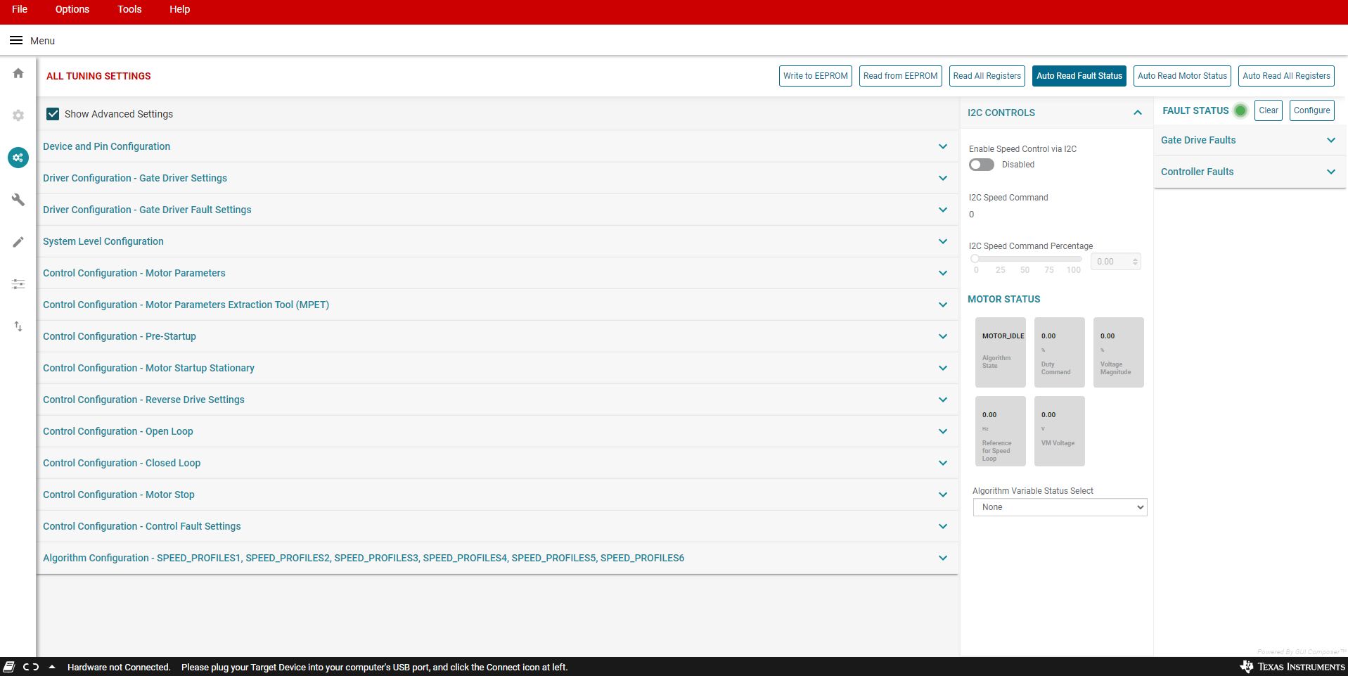
Write the configured values to EEPROM by clicking the "Write to EEPROM" button located at the top right of the MCT8315A GUI. If MCT8315A GUI is not used to program the EEPROM, refer to section 8.6.1.1 in MCT8315A datasheet for the procedure to write to EEPROM via I2C.
Wait for 1-2 seconds. Power cycle MCT8315AEVM by removing the power supply voltage VM and turning it back ON after 3-4 seconds.
Reconnect MCT8315A GUI to MCT8315AEVM. Go to MCT8315A GUI homepage and click the "View Register map" button. Click "Read from EEPROM" button located at the top right of the MCT8315A GUI. Verify the progammed EEPROM values by comparing the programmed values with the values displayed in the "Register map" tab of the MCT8315A GUI.
Apply a nonzero speed command
If the Speed input mode is I2C, change the “I2C Speed Command Percentage” to a non-zero value. Once the speed command is issued, the device will start commutating and the motor should start spinning that is proportional to the I2C Speed Command Percentage.
If the speed input mode is Analog, rotate the Speed Control potentiometer (R4) clockwise to control the motor speed. Once the speed command is issued, the device will start commutating and the motor should start spinning that is proportional to the voltage on the Speed Pin.
If the speed input mode is PWM, apply PWM signal to the speed pin with a given duty cycle with a low of 0 V to a high of 2.2 V (min). Once the speed command is issued, the device will start commutating and the motor should start spinning that is proportional to the duty cycle.
Check if motor spins in closed loop at commanded speed.
In closed loop, the motor should spin at the commanded speed and there should not be any faults triggered.
Enable the “Auto read fault status” toggle button towards the top right corner of the GUI. Then monitor the Fault Status in the side panel to the right.
If no fault gets triggered, skip Section 3.6 and proceed to Section 4.
Prepare device for fault handling if any fault gets triggered.
If the motor failed to spin successfully in closed loop, check the fault status.
Set zero speed command by turning off the PWM, turning the potentiometer completely counterclockwise, or setting the I2C command percentage to 0%.
Clear the fault status registers by clicking on the “Clear” button in the Fault Status side panel to the right as shown in Figure 3-1
This completes the essential controls section. At the end of this section, user should be able to spin the motor in closed loop. Save the register settings by clicking File->Save Registers in the GUI. If there were no faults, skip to Section 4.
 Figure 3-1 Fault Status