SLLU374 November   2024 MCF8329A


  1.   1
  2.   Abstract
  3.   Trademarks
  4. 1Introduction
  5. 2Hardware Design and Setup
    1. 2.1 Board Design
      1. 2.1.1 External MOSFET Selection
      2. 2.1.2 Gate Resistor Selection
      3. 2.1.3 Bootstrap and GVDD Capacitor Selection
      4. 2.1.4 Current Shunt Resistor Selection
      5. 2.1.5 VREG MOSFET Selection
      6. 2.1.6 Additional External Power Stage Components
  6. 3Connecting to the GUI
  7. 4Spinning Into Closed Loop
    1. 4.1 Essential Configuration
      1. 4.1.1 Loading Recommended Default Values
      2. 4.1.2 Setting Base Current
      3. 4.1.3 Setting Current Limits
      4. 4.1.4 Setting Voltage Limits
      5. 4.1.5 Input the Motor's Phase Resistance and Inductance
      6. 4.1.6 Maximum Electrical Speed (Hz)
      7. 4.1.7 Run MPET to Identify Motor Parameters
        1. 4.1.7.1 Skipping MPET Measurements
    2. 4.2 Testing for Successful Startup Into Closed Loop
  8. 5Basic Controls
    1. 5.1 Speed Input Mode
    2. 5.2 Preventing Back Spin of Rotor During Startup
    3. 5.3 Faster Startup Timing
    4. 5.4 Improving Speed Regulation
    5. 5.5 Limiting and Regulating Supply Power
    6. 5.6 MTPA Tuning
    7. 5.7 Motor Studio Optimization Wizards
  9. 6Fault Handling
    1. 6.1 MPET BEMF FAULT [MPET_BEMF_FAULT]
    2. 6.2 Abnormal BEMF Fault [ABN_BEMF]
    3. 6.3 Lock Current Limit [LOCK_LIMIT]
    4. 6.4 Hardware Lock Current Limit [HW_LOCK_LIMIT]
    5. 6.5 No Motor Fault [NO_MTR]
    6. 6.6 Abnormal Speed [ABN_SPEED]

Testing for Successful Startup Into Closed Loop

  1. Apply a nonzero speed command using the slider or text box within the Spin Motor section of the Quick Spin page. Once a speed command is provided, the motor should begin to spin and accelerate until the motor reaches the target speed.
  2. After the motor stops accelerating check that the values in Reference for Speed Loop and Speed FDBK under the Motor Status section are close to the same value.
  3. Check for any faults if the Faults tab shows a red circle. If a fault has been reported, go to Section 6 and follow the debug steps to correct the fault.
  4. Once the motor is able to spin into closed loop and not trigger any faults, stop the motor and save the register configuration to a json file by clicking on File -> Save Registers. In the window that pops up, select Json File and click on the Save Button.
  5. To have configuration for the registers covered in section 7.7 of the MCF8329A data sheet load when the device powers-up these register values can be loaded into EEPROM. To write the configured register values to EEPROM, click the EEPROM drop down located at the bottom right of Motor Studio and select the Write To EEPROM option. Click the Yes button in the window that pops up.
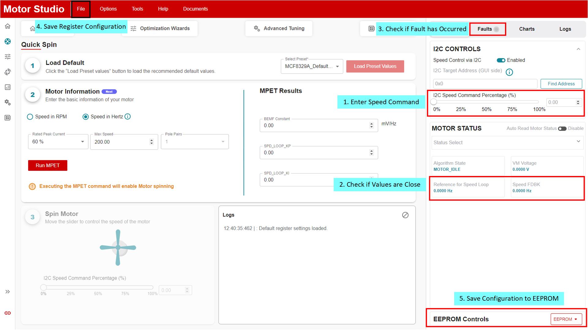
 Closed Loop Spin Test
                    Steps Figure 4-12 Closed Loop Spin Test Steps