SLLU380 March   2024 THVD4411


  1.   1
  2.   Description
  3.   Get Started
  4.   Features
  5.   Applications
  6.   6
  7. 1Evaluation Module Overview
    1. 1.1 Introduction
    2. 1.2 Kit Contents
    3. 1.3 Specification
    4. 1.4 Device Information
  8. 2Hardware
    1. 2.1  Power Requirements
    2. 2.2  Board Setup and Operation
    3. 2.3  Header and Jumper Information
    4. 2.4  Resistor Information
    5. 2.5  Capacitor Information
    6. 2.6  LED Information
    7. 2.7  IC Information
    8. 2.8  Test Points
    9. 2.9  Assembly Instructions
    10. 2.10 Best Practices
  9. 3Hardware Design Files
    1. 3.1 Schematics
    2. 3.2 PCB Layouts
    3. 3.3 Bill of Materials (BOM)
  10. 4Additional Information
    1. 4.1 Known Hardware or Software Issues
    2. 4.2 Trademarks
  11. 5Related Documentation
    1. 5.1 Supplemental Content

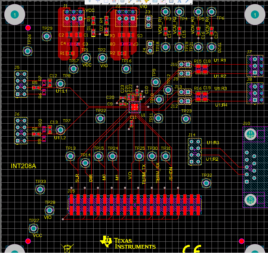
PCB Layouts

GUID-20240229-SS0I-J1T1-SGFV-QJCGQSNXDPQN-low.png Figure 3-5 Top Layer of PCB Layout - THVD4411EVM
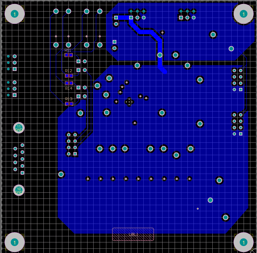
GUID-20240229-SS0I-XKDN-SQL9-M5V6VLHDT9GZ-low.png Figure 3-6 Bottom Layer of PCB Layout - THVD4411EVM
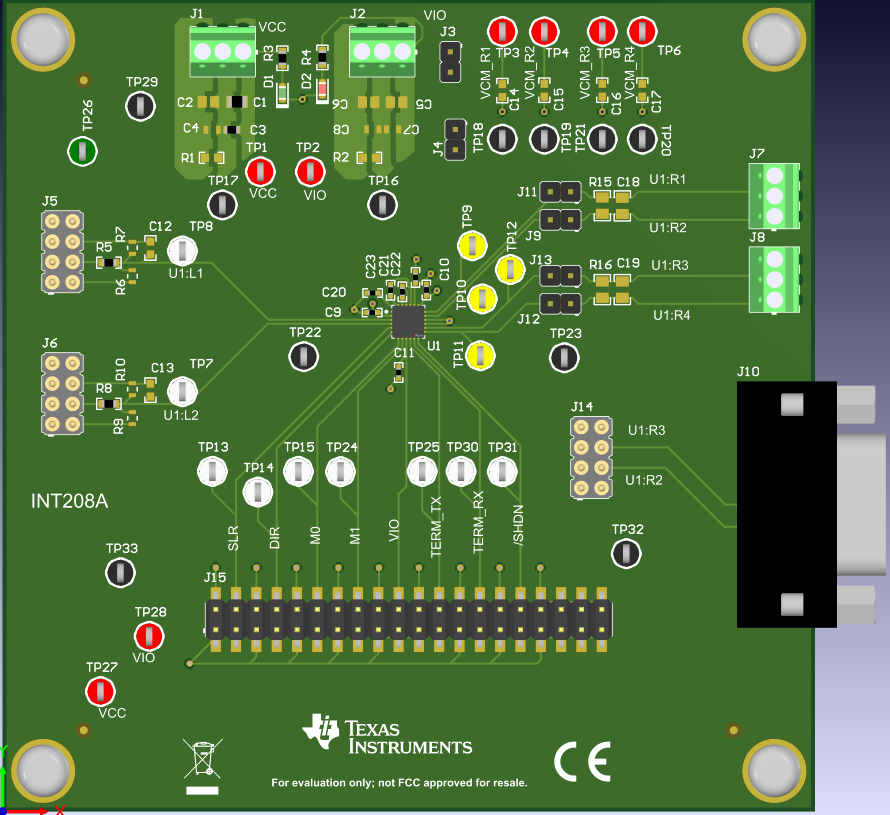
GUID-20240229-SS0I-VMCL-VSWB-TR0WDQKMX54X-low.png Figure 3-7 3D Rendering of Top Layer - THVD4411EVM
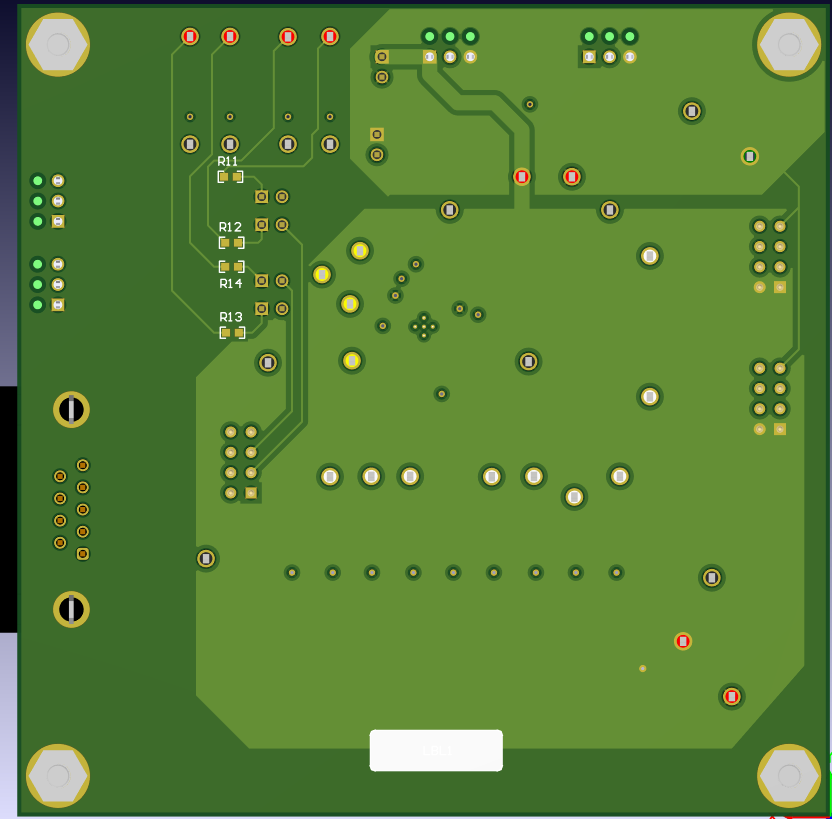
GUID-20240229-SS0I-TJKM-VTWC-KCQZ651JDXT4-low.png Figure 3-8 3D Rendering of Bottom Layer - THVD4411EVM
GUID-20240229-SS0I-CVT6-DSKT-Q3T6FZN5XFMF-low.png Figure 3-9 PCB Layer Stackup Information