Benefits of Auto-Resonance Tracking
Trademarks
All trademarks are the property of their respective owners.
1 Introduction
The DRV260x and DRV262x families of devices use a unique LRA control algorithm called auto-resonance tracking. Auto-resonance tracking uses the back-EMF of an LRA to detect and track the resonance frequency. The DRV260x and DRV262x devices then uses this resonance frequency information to drive the LRA in closed loop. Auto-resonance provides numerous benefits and eases the integration of LRAs:
- Stronger and more consistent vibrations across actuators
- Lower power consumption while driving at resonance
- The ability to overdrive and brake an LRA and achieve better response time
Figure 1-1 shows the input and output signals in an auto-resonance tracking system.
 Figure 1-1 LRA Auto-Resonance Detection
The green waveform is the (PWM) input to the DRV2605 and is a filtered PWM-modulated DC signal representing the waveform envelope or amplitude of the output waveform. The black line represents the sine wave output generated by the DRV2605 with the detected resonant frequency. The DRV2625 does not have a PWM input but the same functionality is achieved using the Real Time Playback (RTP) registers of the device, where instead of setting a physical voltage level on a pin you would set a voltage level via an 8-bit value using I2C.
2 How Auto-Resonance Tracking Works
Auto-resonance tracking takes advantage of the back-EMF generated by an LRA to determine the resonant frequency. TI has characterized this back-EMF to determine how best to control the LRA frequency, vibration strength, and start and stop time.
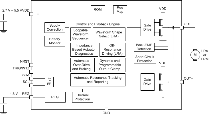
 Figure 2-1 DRV2605 Block Diagram
 Figure 2-2 DRV2625 Block Diagram
Auto-resonance tracking makes use of the electro-mechanical properties of an LRA. Inside the LRA, the back-EMF changes as the magnet moves closer or further away from the drive electrodes. This back-EMF signal is sensed on the output pins by the DRV2605 and DRV2625 every cycle and sent to the auto-resonance engine. The auto-resonance engine then determines the frequency.
If the frequency is too high, the DRV2605 and DRV2625 will reduce the output frequency, and if the frequency is too low, the DRV2605 and DRV2625 will increase the output frequency. This dynamic tracking will ensure more consistent vibration. Consistent vibration is much harder to achieve with a non-auto-resonance drivers, because the LRA resonant frequency can constantly vary as a result of manufacturing tolerances and environmental factors. Having real-time tracking of the resonant frequency is important to keep a strong, consistent vibration. DRV2604 and DRV2624 Behave identically with the exception of having internal RAM vs ROM which does not impact the auto-resonance feature.