SLOA294A June 2020 – April 2024 TPS3851-Q1 , TPS7A16A-Q1
- 1
- Abstract
- Trademarks
- 1 Introduction
- 2 Types of Faults and Quantitative Random Hardware Failure Metrics
- 3 Random Failures Over a Product Lifetime and Estimation of BFR
- 4 BFR Estimation Techniques
- 5 Siemens SN 29500 FIT model
- 6 IEC TR 62380
- 7 Recommended Assumptions for BFR Calculations
- 8 Special Considerations for Transient Faults
- 9 BFR Differences (Due to Package) Between IEC TR 62380 and SN 29500
- 10Effect of Power-on Hours on BFR
- 11What Can You Expect for TI Products
- 12Summary
- 13References
- 14Revision History
6 IEC TR 62380
The IEC 62380 standard is also commonly used when estimating BFR in functional safety analysis. It is a reliability data handbook that outlines a universal model for predicting the reliability of electronic components, printed circuit boards (PCBs) and equipment. It was published in 2004, and subsequently obsoleted. However, the ISO 26262 standard (now in second edition, revised in 2018) has incorporated the IEC 62380 standard as part of the newly published Part 11 – Guidelines on Application of ISO 26262 to Semiconductors.
The IEC TR 62380 IC failure rate can be modeled as sum of the die, package and electrical overstress (EOS) related failure rates, where:
- The die-related failure rate formula includes terms for IC type and IC technology, transistor count, thermal mission profile, junction temperature, and operating and non-operating lifetime.
- The package-related failure rate formula includes terms for mechanical stress caused by thermal expansions, thermal cycles, thermal mission profile, package type and package materials.
- The EOS failure rate formula includes terms for specific systems with an external interface and electrical environment.
Equation 1 shows the IEC TR 62380 BFR formula (reproduced from the original standard). System integrators must refer to the IEC 62380 standard to access the information required to calculate BFR.
Equation 2 expresses the die FIT according to IEC TR 62380 as:
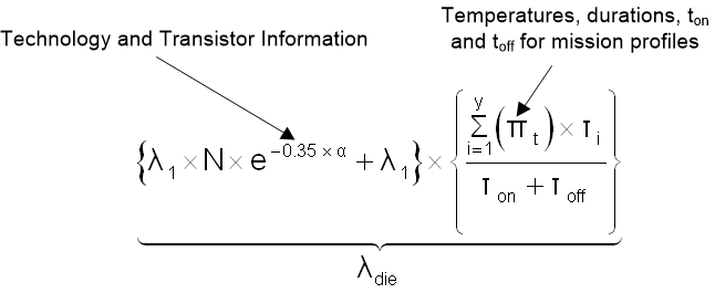
- where N is the number transistor by type, λ1 is the transistor type scale factor, λ2 is the technology base fit rate and α is a factor for the current year of manufacture.
Equation 3 expresses the package FIT according to IEC TR 62380:
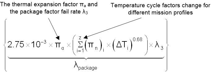
- where πα is the difference in thermal expansion coefficients of the IC vs. the PCB and λ3 is the package scale factor by package type and size.
Equation 4 expresses the EOS FIT according to IEC TR 62380:
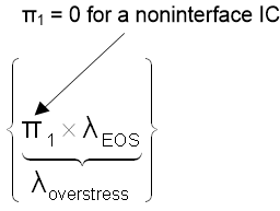
- where the default assumption is that EOS = 0.
If the IC application is listed in the table and the system has an external connection between the IC on the circuit board and the outside environment, then system integrators can add EOS values as needed.
Table 6-1 reflects data from a table for an automotive mission profile according to IEC TR 62380. According to this table, the overall working time for an automotive motor control application is approximately 500 hours per year with four day time starts, two night time starts, and 30-days a year of non-use.
|
Mission Profile Phases |
Temp. 1 |
Temp 2. |
Temp. 3 |
Ratios on/off |
2 Night Starts |
4 Day Light Starts |
Non-Used Vehicle |
|||||||
|---|---|---|---|---|---|---|---|---|---|---|---|---|---|---|
|
Application Types |
(tac)1 °c |
t1 |
(tac)2 °c |
t2 |
(tac)3 °c |
t3 |
ton |
toff |
n1 Cycles/year |
∆T1 °C/cycle |
n2 Cycles/year |
∆T2 °C/cycle |
n2 Cycles/year |
∆T3 °C/cycle |
|
Motor Control |
32 |
0.020 |
60 |
0.015 |
85 |
0.023 |
0.058 |
0.942 |
670 |
 |
1340 |
 |
30 |
10 |
|
Passenger Compartment |
27 |
0.006 |
30 |
0.046 |
85 |
0.006 |
0.058 |
0.942 |
670 |
 |
1340 |
 |
30 |
10 |