SLOA317 November 2021 DRV8311
3 tSPI Interface and Applications
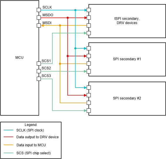
The tSPI interface uses the same physical protocol as SPI. That means it has four wires for clock, input, output, and chip select. This is easily compatible with MCUs. The key difference is that the tSPI protocol allows random access to secondary devices from the primary device via common wires. Up to 15 tSPI devices can be managed through a common chip select. tSPI devices can be used in conjunction with other independent SPI devices connected to the MCU as secondary devices, making it relatively simple to add to existing systems from a hardware perspective as shown in Figure 3-1.
 Figure 3-1 Example of tSPI Integration
into Independent Secondary SPI System
Figure 3-1 Example of tSPI Integration
into Independent Secondary SPI SystemThere are numerous benefits to tSPI protocol on an interface level. For example:
- Random secondary access is permitted, so read and write operations can be performed in any order between secondary devices, which is important for multi motor control.
- There is a provision for a general call address to command all secondary devices managed by the tSPI interface simultaneously, which can be helpful for functions such as starting multiple motors together.
- There is no requirement for all tSPI secondary devices to be active at all times. The interface can successfully perform transactions with any active secondary device regardless of the status of the other devices
The only disadvantage of tSPI is the additional 8 bits of header overhead within a data frame compared to a typical independent SPI implementation, at 32 bits versus 24 bits. More details about the tSPI interface can be found in the data sheet for the DRV8311.
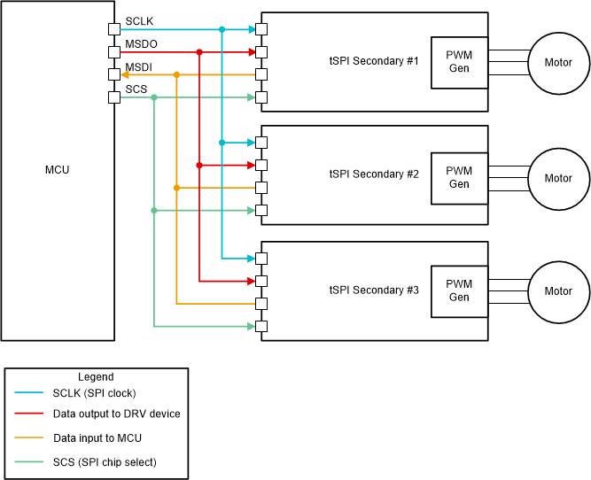
Having discussed the operation of tSPI and the workings of the interface, we can now discuss its benefits in multi-motor control applications. As discussed earlier, a typical hardware setup for motor control applications involves connecting an MCU to multiple PWM pins, which can then be manipulated to control the speed and direction of the motor. For a multi-motor control application, it is possible to use one tSPI device such as a DRV8311 to manage 3 or 6 PWM pins corresponding to a single motor. Multiple such tSPI devices can then be connected to the MCU for a comprehensive and convenient multi-motor application, as shown in Figure 3-2.
 Figure 3-2 Example of tSPI Devices in a
Multi-Motor Control Application
Figure 3-2 Example of tSPI Devices in a
Multi-Motor Control ApplicationIn this example, the three motors can be controlled by a common chip select and the MCU only needs 4 wires total. A given motor can be manipulated by sending in write commands to the corresponding tSPI device that is managing its motor driver, which will then lead to appropriate changes in the PWM pins. In general, the formula for the reduction in wires compared to the standard approach is (N * PWMx – 4), where N is the number of motors in the design and PWMx is the number of PWM pins required by each motor, previously discussed to be either 3 or 6. The wire savings can be very significant when multiple motors are present, helping to keep the overall design simple, compact, and easy to manufacture. The reduction in required MCU wiring also allows for more MCU pins to be allocated for other purposes, or perhaps the selection of a smaller MCU depending on the project.