SLOK014A November 2018 – August 2024 TLV1704-SEP
3 Test Device and Test Board Information
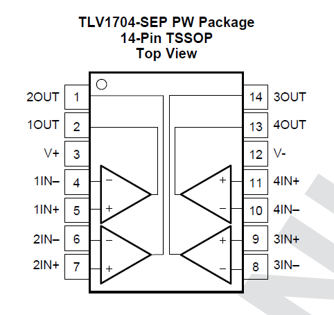
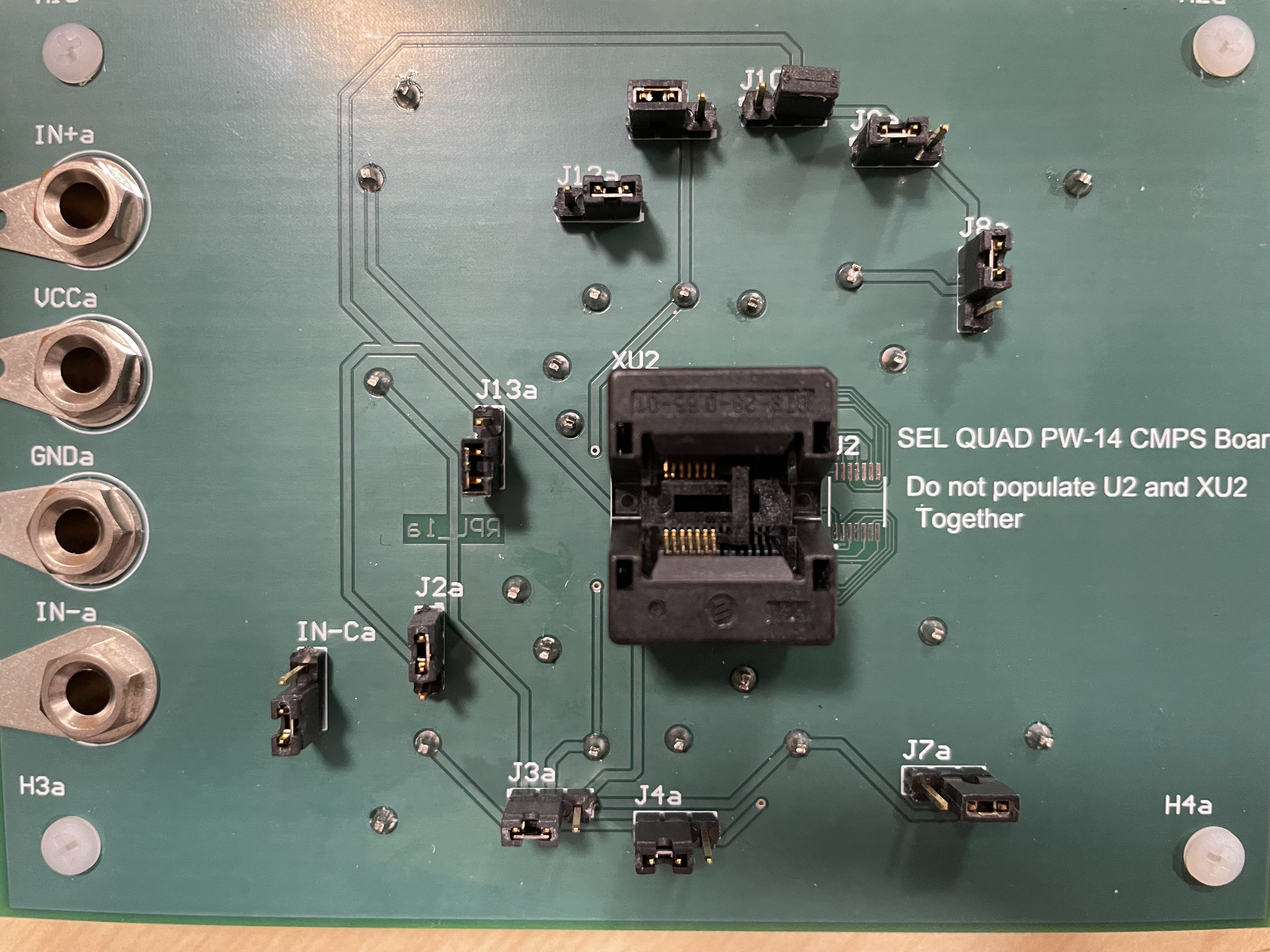
The TLV1704-SEP is packaged in a 14-pin, TSSOP shown with pinout in Figure 3-1. The TLV1704-SEP bias board is used for the SEE characterization is shown in Figure 3-2 and bias diagram in Figure 3-3.

Qualification Devices and Test
The TLV1704-SEP was biased in either an output high or output low condition in single supply, where V+ was set to 24V and V- was set to GND (0V). All non-inverting inputs of each channel were tied together; likewise, all inverting inputs of each channel were tied together. To achieve an output high state, IN+ was biased with 3V and IN- was biased with 2V. For an output low condition, IN+ was biased with 2V and IN- was biased with 3V. A nominal flux of 105 ions / s-cm2 and fluence of 107 ions / cm2 were used for each run during the exposure at 125°C.
 Figure 3-2 TLV1704-SEP Bias Board
 Figure 3-3 TLV1704-SEP Bias
Diagram