SLOU571 June 2024
- 1
- Description
- Get Started
- Features
- Applications
- 6
- 1Evaluation Module Overview
- 2Hardware
- 3Hardware Design Files
- 4Additional Information
2.1.6.3 DRV8421B: Brushed-DC Motor Control
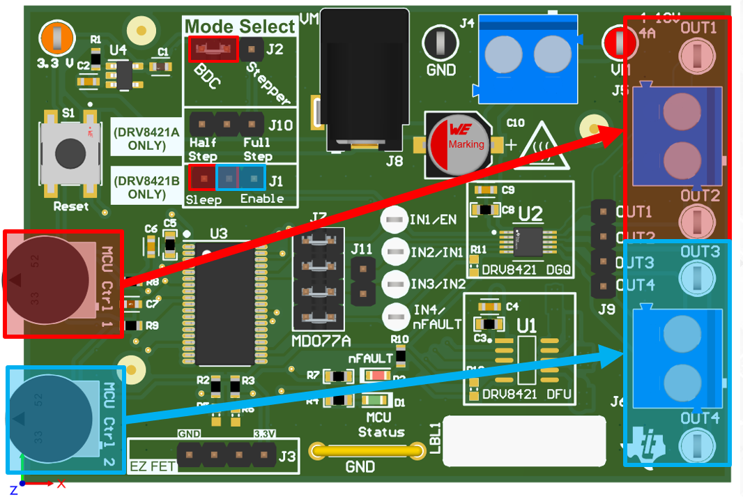
The MSP430 produces PWM signals for the IN1 and IN2 pins with duty cycles proportional to the voltage from the MCU Ctrl 1 and MCU Ctrl 2 potentiometers. To achieve a 1 or 0 for the outputs, the input potentiometers must be turned completely clockwise or counterclockwise. The table below shows how to configure the input potentiometers for different modes of operation.
|
EN |
IN1 |
IN2 |
OUT1 |
OUT2 |
OUT3 |
OUT4 |
Description |
|
|---|---|---|---|---|---|---|---|---|
|
0 |
X |
X |
OFF |
OFF |
OFF |
OFF |
Low-power sleep mode |
|
|
1 |
Low – turn MCU CTRL 1 completely counter-clockwise |
X |
1 |
0 |
X |
X |
Channel 1 |
Forward |
|
1 |
High – turn MCU CTRL 1 completely clockwise |
X |
0 |
1 |
X |
X |
Channel 1 |
Reverse |
|
1 |
X |
Low – turn MCU CTRL 2 completely counter-clockwise |
X |
X |
1 |
0 |
Channel 2 |
Forward |
|
1 |
X |
High – turn MCU CTRL 1 completely clockwise |
X |
X |
0 |
1 |
Channel 2 |
Reverse |
 Figure 2-11 EVM Controls for Brushed-DC
Motor Operation with DRV8421B