SLOU571 June 2024
- 1
- Description
- Get Started
- Features
- Applications
- 6
- 1Evaluation Module Overview
- 2Hardware
- 3Hardware Design Files
- 4Additional Information
2.1.6.1 DRV8421A: Brushed-DC Motor Control
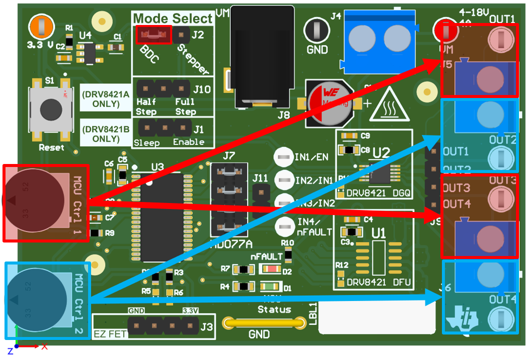
The MSP430 produces PWM signals for the IN1, IN2, IN3 and IN4 pins with duty cycles proportional to the voltage from the MCU Ctrl 1 and MCU Ctrl 2 potentiometers. To achieve a 1 or 0 for the outputs, the input potentiometers must be turned completely clockwise or counterclockwise. The table below shows how to configure the potentiometers for different modes of operation.
| IN1/IN3 | IN2/IN4 | OUT1 | OUT2 | OUT3 | OUT4 | FUNCTION |
|---|---|---|---|---|---|---|
|
Low – turn MCU CTRL 1 completely counter-clockwise |
Low – turn MCU CTRL 2 completely counter-clockwise |
Hi-Z |
Hi-Z |
Hi-Z |
Hi-Z |
Standby Mode (Hi-Z) |
|
High – turn MCU CTRL 1 completely clockwise |
Low – turn MCU CTRL 2 completely counter-clockwise |
1 |
0 |
1 |
0 |
Forward |
|
Low – turn MCU CTRL 1 completely counter-clockwise |
High – turn MCU CTRL 2 completely clockwise |
0 |
1 |
0 |
1 |
Reverse |
|
High – turn MCU CTRL 1 completely clockwise |
High – turn MCU CTRL 2 completely clockwise |
0 |
0 |
0 |
0 |
Brake |
Due to the limitation of two inputs, the EVM firmware in place is only configured to control two outputs. Separate firmware must be configured on an external MCU with inputs connected to J7 to utilize all four outputs with independent half-bridge control.
 Figure 2-6 EVM Controls for Brushed-DC
Motor Operation with DRV8421A