SLUA887A August 2018 – September 2023 LM2005 , LM2101 , LM2103 , LM2104 , LM2105 , LM25101 , LM27222 , LM2724A , LM5100A , LM5100B , LM5100C , LM5101 , LM5101A , LM5101B , LM5101C , LM5102 , LM5104 , LM5105 , LM5106 , LM5107 , LM5108 , LM5109 , LM5109A , LM5109B , LM5109B-Q1 , LM5113-Q1 , LMG1205 , LMG1210 , SM72295 , SM74104 , TPS28225 , TPS28225-Q1 , TPS28226 , TPS2832 , TPS2836 , TPS2837 , UC2950 , UCC27200 , UCC27200-Q1 , UCC27200A , UCC27201 , UCC27201A , UCC27201A-DIE , UCC27201A-Q1 , UCC27211 , UCC27211A , UCC27211A-Q1 , UCC27212 , UCC27212A-Q1 , UCC27222 , UCC27282 , UCC27282-Q1 , UCC27284 , UCC27284-Q1 , UCC27288 , UCC27289 , UCC27301A , UCC27301A-Q1 , UCC27311A , UCC27311A-Q1 , UCC27710 , UCC27712 , UCC27712-Q1 , UCC27714
3.3 External Bootstrap Diode
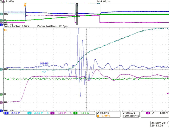
In order to minimize losses associated with the reverse recovery properties of the diode and ground noise bouncing, a fast recovery diode or Schottky diode with low forward voltage drop and low junction capacitance is recommended. Using Schottky diodes reduce the risk associated with charge supplied back to the gate driver supply from the bootstrap capacitor and minimize leakage current. Figure 3-1, shows the reverse recovery losses when using diodes with reverse recovery times on HB-HS(Ch1). We can observe large amount of over and undershoot on the HB-HS pin which can trigger the driver's UVLO and shutdown the gate driver.
When the HS pin (switch node) is pulled to a higher voltage, the diode must be able reverse bias fast enough to block any charges from the bootstrap capacitor to the VDD supply. This bootstrap diode should be carefully chosen such that it is capable of handling the peak transient currents during start-up; and such that its voltage rating is higher than the system DC-link voltage with enough margins.
 Figure 3-1 Reverse Recovery Losses due to Bootstrap Diode Reverse Recovery Time
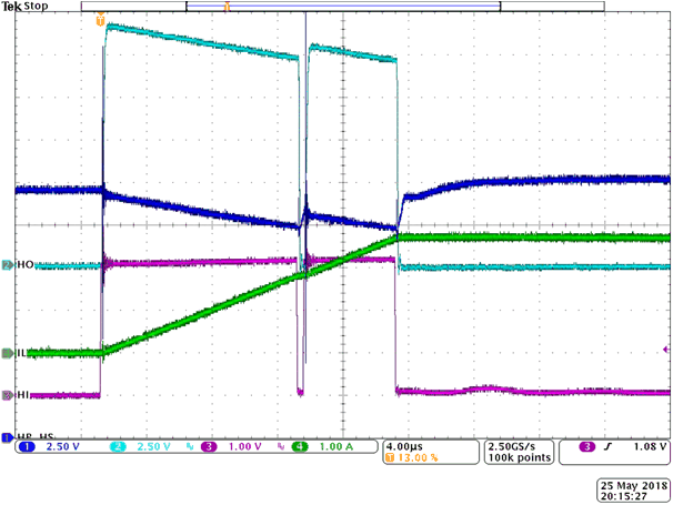
Figure 3-2 below shows a reverse recovery condition created (channel 1) by setting up the timing to specifically force the switch node high with the diode current flowing.
 Figure 3-2 Reverse Recovery Losses due to Bootstrap Diode Reverse Recovery Time (Zoomed Out)