SLUA888 May 2018 TPS53622 , TPS53659 , TPS53679 , TPS53681
-
NVM Programming for VR13 Power Controllers
- Trademarks
- 1 Introduction
- 2 Technical Overview
- 3
Use of TI Programming Tools
- 3.1
Fusion Digital Power Designer
- 3.1.1 Build and Export a System (.tifsp) File
- 3.1.2 View a Project File or System File Offline
- 3.1.3 Import a Project File to a Single Online Device
- 3.1.4 Import a System File to an Online System
- 3.1.5 Export CSV Script for Third Party Tools
- 3.1.6 Compare Two Project Files
- 3.1.7 Build a System File from Existing Project Files
- 3.2 Fusion Manufacturing Tool
- 3.3 TI Programming Board
- 3.1
Fusion Digital Power Designer
3.1.1 Build and Export a System (.tifsp) File
The Fusion Digital Power Designer software has a convenient graphical interface to configure and test TI VR13 controllers.
An more detailed discussion of each parameter in the GUI can be found in the application report Using the Fusion Digital Power Designer for TPS536xx VR13 Multiphase Solutions. Contact vr@list.ti.com for more information.
- Connect the USB-GPIO adapter to either a system board, or socketed programming board with a TI VR13 controller on-board.
- Apply 3.3 V to the V3P3 pins of the controller devices. It is not necessary to apply 5-V and 12-V power. Make sure to disable power conversion. You may need to pull the AVR_EN/BEN pins low to stop power conversion.
- Start the Fusion Digital Power Designer software.
- Click Change Scanning Modes, then select DEVICE_ID & DEVICE_CODE & IC_DEVICE_ID if the software does not recognize your device.
- From the System View, click Click to Configure Device to view individual controller devices.
- Click on Write to Hardware to set write the values to the device
- Click Store Config. to NVM to store the NVM settings.
- Click Device Menu
- Click Refresh All Parameters to update USER_DATA commands in the GUI.
- Select Save Project As from the File menu to export a Project file for a single device.
- Repeat steps 5 through 14 for each device.
- To set NVM values for another device, return to the System View page and Click to Configure Device.
- To save a System file after all devices are configured, return to the System View click the File menu and select, Save System File As.
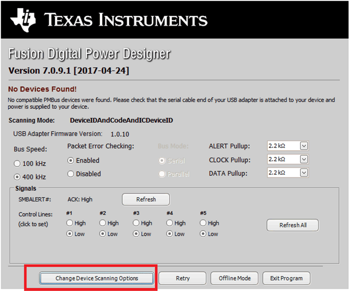 Figure 8. Change Scanning Modes
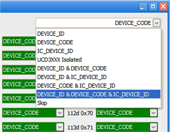 Figure 9. Scanning Mode Selections
The application report, Using the Fusion Digital Power Designer for TPS536xx VR13 Multiphase Solutions contains detailed information about NVM configuration for TI VR13 multiphase controllers.
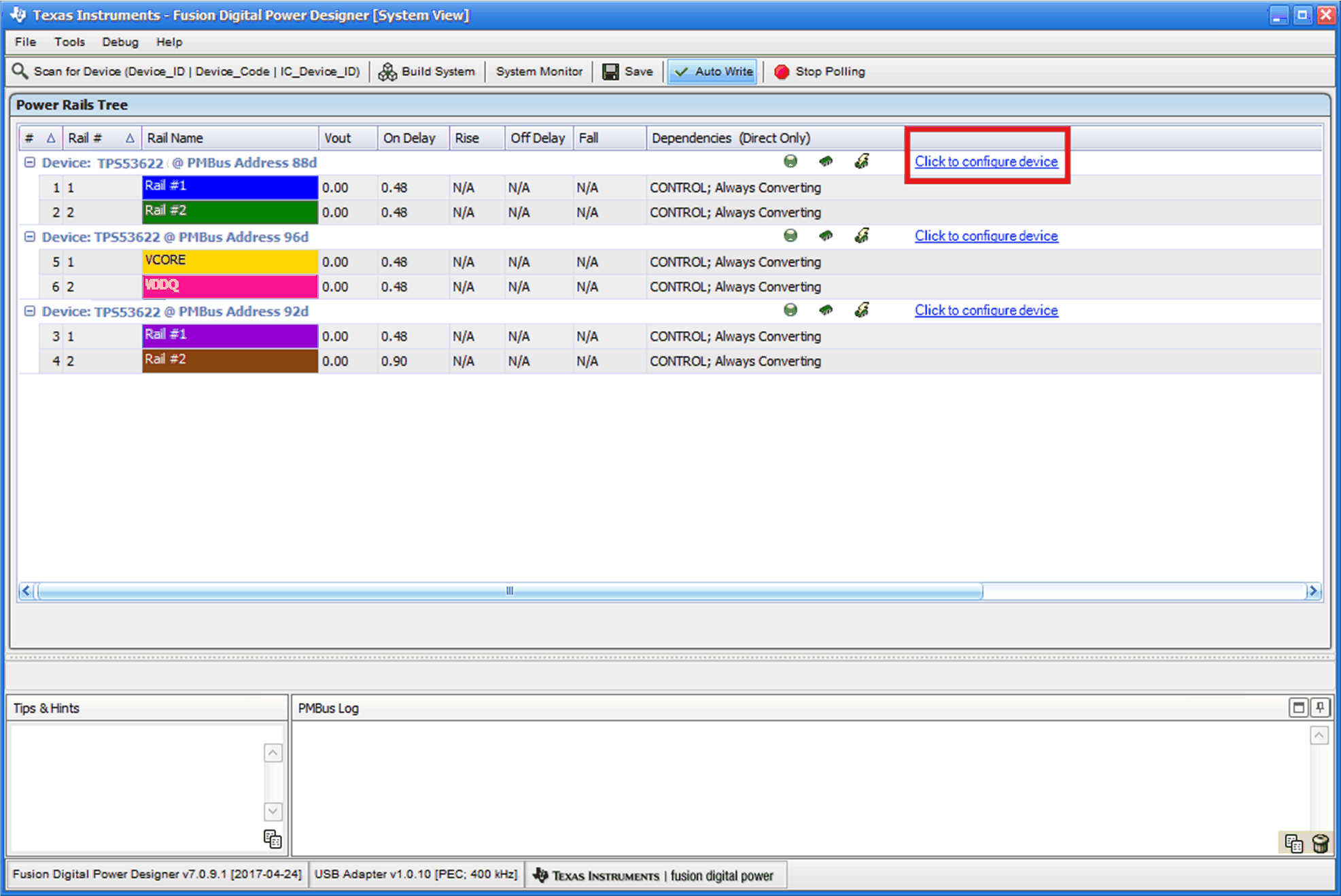 Figure 10. System View
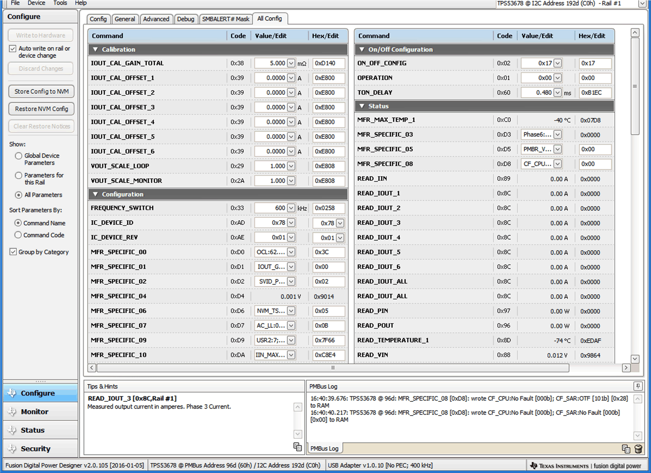 Figure 11. Settings for Individual Device
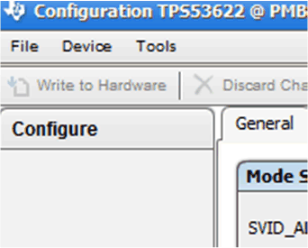 Figure 12. Write to Hardware
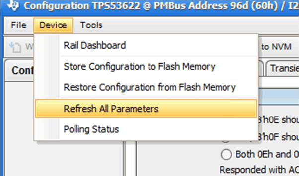 Figure 13. Refresh All Parameters
 Figure 14. Switch between Multiple Devices
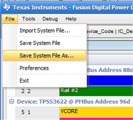 Figure 15. Save a System File