SLUA888 May 2018 TPS53622 , TPS53659 , TPS53679 , TPS53681
-
NVM Programming for VR13 Power Controllers
- Trademarks
- 1 Introduction
- 2 Technical Overview
- 3
Use of TI Programming Tools
- 3.1
Fusion Digital Power Designer
- 3.1.1 Build and Export a System (.tifsp) File
- 3.1.2 View a Project File or System File Offline
- 3.1.3 Import a Project File to a Single Online Device
- 3.1.4 Import a System File to an Online System
- 3.1.5 Export CSV Script for Third Party Tools
- 3.1.6 Compare Two Project Files
- 3.1.7 Build a System File from Existing Project Files
- 3.2 Fusion Manufacturing Tool
- 3.3 TI Programming Board
- 3.1
Fusion Digital Power Designer
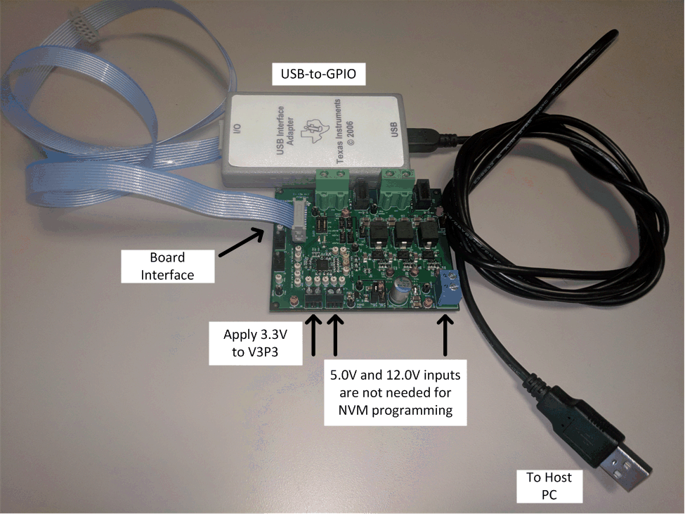
2.1 Hardware Connections
You can program NVM on a fully-populated application board. However, successful programming requires only a few connections be made to these devices. In some cases offline gang-programming in socketed boards works better than a full In Circuit Test (ICT) solution.
Table 2. Hardware Connections for Offline NVM Programming
| Pin Name | Connection |
|---|---|
| V3P3 | Connect to +3.3V supply, and bypass with a minimum of 1.0 µF to ground. |
| VREF | Bypass to ground with a minimum of 1.0 µF to ground. |
| ADDR | Connect a resistor divider from VREF to ADDR to Ground to set the PMBus address (required for programming), as described in the product datasheet. |
| SMB_DIO, SMB_CLK | Connect to programming host, pull-up to 3.3V with a 2.2 kΩ resistor. Note, the TI USB-to-GPIO interface adapter has internal pull-up resistors. |
| ATSEN, BTSEN, TSEN | Not used for NVM programming. Tie-off with a 1:1 resistor divider from VREF to TSEN to Ground, suggested resistor value is 49.9 kΩ. This sets the pin voltage to appx. 0.85 V, which the controller device interprets as 32°C. |
| AVR_EN, BVR_EN, VIN_CSNIN, CSPIN, AVSP, BVSP, AVSN, BVSN | Not used for NVM programming. Tie-off to ground. |
| ACSPx, BCSPx | Not used for NVM programming. Tie off to VREF. |
| APWMx, BPWMx, ASKIP, BSKIP, VRFAULT, SMBALERT, SALERT, PIN_ALT, SDIO, SCLK | Not used for NVM programming. Float these pins if not used. |
 Figure 1. Hardware Connections