SLUA987C October 2019 – February 2023 UCC27531-Q1 , UCC28700-Q1 , UCC28730-Q1 , UCC28740-Q1 , UCC28C40-Q1 , UCC28C41-Q1 , UCC28C42-Q1 , UCC28C43-Q1 , UCC28C44-Q1 , UCC28C45-Q1 , UCC57102-Q1 , UCC57108-Q1
1 Introduction
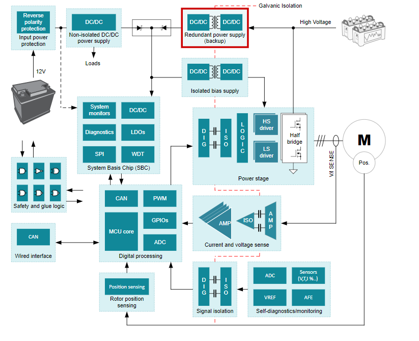
The traction inverter efficiently converts DC power from a high-voltage battery to alternating phases of power needed to drive multi-phase motors. Galvanic isolation is required to protect people, as well as the low-voltage components on the cold side of the system, from the high-voltage traction inverter on the hot side of the system. As automotive applications continue to trend in the direction of increased safety, it has become more common to include a high-voltage to low-voltage backup supply in the traction inverter system. The backup power supply powers the low-voltage components if the 12-V battery fails or the HV battery gets disconnected. #T6011291-2 displays an example block diagram featuring the high-voltage to low-voltage redundant power supply.
 Figure 1-1 Traction Inverter Block Diagram
The flyback topology works for the redundant power supply because low cost, isolation, and flexibility. A flyback controller such as the UCC28C56H-Q1, or the UCC28700-Q1, is suitable for this application. For systems requiring the highest efficiency and power density, the UCC28781-Q1 offers higher switching frequency, direct synchronous rectifier FET control, zero-voltage switching for minimal switching losses and EMI, and programmable adaptive burst mode for light and no load conditions.
The high-voltage input flyback converter needs to support ultra-wide input voltages. The backup supply may be required to operate down to between 40 V to 60 V depending on the architecture. This auxiliary supply can enable active discharge for the DC link capacitors or active short circuit for the motor. HV transients on the DC bus can exceed 1 kV in amplitude while lasting a few seconds, so a 1 kV maximum input-voltage may be required in 800-V battery systems for margin. In these cases, the analog controller and transformer selected must be designed accounting for limits on duty cycles and minimum on times, without sacrificing regulation accuracy or transient response, across the full load range.
Functional safety requirements dictate measures that protect testers and end users from potential risks during specific operating conditions. So, the powering the HV-LV backup supply from 800 V instead of 400 V presents new and interacting design challenges. More specifically, these challenges are designing for ultra-wide input voltage range, with automotive rated HV power devices, and optimizing design performance based on cost and size constraints while ensuring the system meets safety requirements among others.