SLUAA16A August 2020 – October 2023 BQ79600-Q1
1.5 Communication to Battery Monitor Device (COMHP, COMHN, COMLP, COMLN pins)
COMHP, COMHN, COMLP and COMLN pins are AC coupled bi-directional input/output pins used for communication with TI's battery monitor ICs such as the BQ7961X-Q1 family of devices. To communicate in the North direction, COMHP/N differential pins of BQ79600-Q1 should be connected to the COMLP/N pins of the first battery monitor IC in the stack through proper isolation. Likewise, to communicate in the South direction, such as when ring architecture is used, COMLP/N differential pins of BQ79600-Q1 should be connected to the COMHP/N pins of the top of stack battery monitor IC through proper isolation. Leave these pins unconnected if not used.
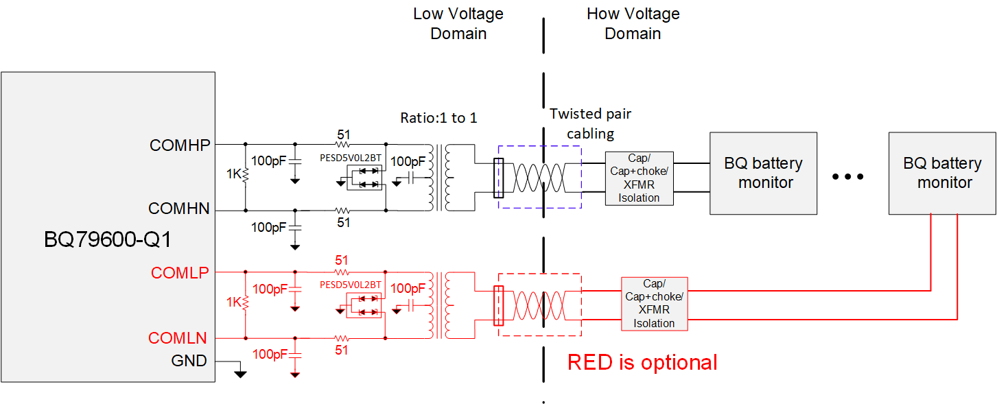
To isolate between the low voltage system and the high voltage domain, transformer isolation is recommended as it is the most effective method for removing common mode noise from the system. Figure 1-5 shows the interface components values. The circuit shown in red is only needed if ring architecture is used.
 Figure 1-5 Daisy Chain Isolation
The benefit of using the ring architecture is that the host can continue communicating with the battery monitor stacked devices even when there is a break on the communication line between two stacked devices. In a non-ring scheme, a break between 2 devices would prevent communication to all upstream devices. When a ring architecture is used with BQ79600-Q1 bridge device and BQ7961X-Q1 stacked devices, if the host detects a broken communication interface it would be able to switch the communication direction to communicate with devices on both sides of the break. This allows for safe operation until the break in the lines is repaired. Steps on how to reverse the communication direction when ring architecture is used can be found in the device's data sheet.
Ring architecture also enables fault status transmitting when the BQ7961X-Q1 stacked devices are in SLEEP mode and BQ79600-Q1 is either in SLEEP mode or SHUTDOWN mode.
| Component | Purpose | Recommendation |
|---|---|---|
| Transformer | Transformer provides galvanic isolation between the Low Voltage and High Voltage domains. | HMU1228NL Transformer or HM2147NL Transformer. |
| Termination resistor | The purpose of this resistor is to prevent reflected signals from interfering in the communication. | 1 KΩ resistor between COMHP and COMHN pins. If ring architecture used, 1 KΩ resistor between COMLP and COMLN pins. There should be a termination resistor at each end of the connection on the BQ79600-Q1 side and on the BQ7961X-Q1 side. |
| Series resistor | Series termination resistance for impedance matching. | 51 Ω series resistor on both COMHN and COMNP lines as shown in Figure 1-5. If ring architecture used, also need 51 Ω series resistor on both COMLN and COMLP lines. |
| Bypass capacitors | Bypass capacitors to provide filtering as well as improving performance during BCI testing. | 100 pF/50 V capacitor to GND on both COMHN and COMHP. If ring architecture used, 100 pF/50 V capacitor to GND on both COMLN and COMLP. |
| ESD protection | It is recommended that ESD protection is added to provide ESD isolation on the communication lines. | PESD5V0L2BT ESD device. |
| Capacitor on transformer center terminal | Transformer needs to be center tapped with a 100 pF capacitor. | 100 pF/50 V capacitor. |
In all of these situations, the recommendation is based on how long the cable between boards is, and in all cases, twisted pair cabling is used between modules. The main purpose of these noise isolation methods is to remove common mode noise from the signal.
Any capacitance present on the communication line will have an effect on the performance. All intentional and parasitic capacitance should be calculated and taken into account.