SLUAA51 October 2020 LMR50410
2 Understanding of Loop Stability Test
The purpose of a loop stability test is obtaining Bode plot of the open-loop transfer function in a closed-loop DC-DC converter. Consider a normally working converter circuit with a voltage feedback, shown in Figure 2-1(a).
 Figure 2-1 (a) DC-DC Converter with
Closed-loop Control (b) DC-DC Converter with Open-loop Control
Figure 2-1 (a) DC-DC Converter with
Closed-loop Control (b) DC-DC Converter with Open-loop ControlIn Figure 2-1(a) the feedback voltage directly comes from output voltage and controls the same output simultaneously, making the converter a closed loop. Now make the top-side feedback resistor not connected to output voltage but to an external voltage source V'OUT as shown in Figure 2-1(b). Then output voltage will be automatically adjusted to V'OUT. If V'OUT is equal to VOUT, the working status in Figure 2-1(a) and (b) are exactly the same.
 Figure 2-2 Open-loop Feedback with AC
Voltage Injection
Figure 2-2 Open-loop Feedback with AC
Voltage InjectionConsider an extra AC voltage source with small amplitude VINJ applied in series with the external source, shown in Figure 2-2, then there will be an AC component VAC in feedback voltage and thus output voltage VOUT will also have an AC component VR. VR and VINJ normally have different amplitude and are out-of-phase but their frequencies are same which are much lower than switching frequency of the converter. So the open-loop transfer response in both Figure 2-1(b) and (a) can be expressed in Equation 3.

The circuit in Figure 2-2 can be considered as basis of any loop stability test methods for DC-DC converters, in another word, any loop stability test circuits should be equivalent to it. Otherwise the test will lead to a wrong Bode plot.
When the above circuit is directly applied in a practical loop stability test, several high-precision measuring equipments are needed. Thus some simplifications are applied and here consider the circuit in Figure 2-3.
 Figure 2-3 An Equivalent Closed-loop
Connection with AC Voltage Injection
Figure 2-3 An Equivalent Closed-loop
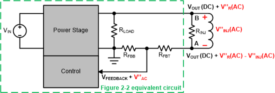
Connection with AC Voltage InjectionIn Figure 2-3 circuit, when the AC voltage V'INJ is inserted in the closed-loop, there will be AC components with same frequency anywhere in the loop including output voltage, shown as V'R. Here RFBT will see an AC component as V'R + V'INJ which is exactly equivalent to the VINJ in Figure 2-2 because V'R and V'INJ have a same frequency. The part of Figure 2-3 circuit circled with dash line is actually the same as Figure 2-2 circuit.
 Figure 2-4 An Equivalent Closed-loop
Connection with Frequency Response Analyzer
Figure 2-4 An Equivalent Closed-loop
Connection with Frequency Response AnalyzerIn a practical loop stability test, the connection outside dash line circle in Figure 2-3 is achieved by a frequency response analyzer, shown in Figure 2-4. The equivalent relations from Figure 2-2 to Figure 2-4 are described in the following equations.


The frequency response analyzer only collects and processes AC components of voltages at point A and B, so Equation 3 can be expressed in Equation 6:

When a frequency sweeping of injection signal is finished by analyzer, the gain and phase curves of GOPEN(s) in Equation 6 will be displayed as the Bode plot of the converter loop.