SLUAA69 July 2020 – MONTH TPS548D22
2 Principle of Synchronous Buck with Sinking Current Application
The basic steady state operations of synchronous buck with sourcing current (general use) and sinking current at full load are shown in Figure 2-1 and Figure 2-2. The behaviors of the sinking current case are opposite that of the sourcing current case. The inductor current flows in reverse. The currents of both the high-side and low-side MOSFET flow from source to drain. In addition, the inductor is charged when the low-side MOSFET is ON and the high-side MOSFET is OFF. The inductor is discharged and freewheeling when the low-side MOSFET is OFF and high-side MOSFET is ON.
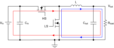 Figure 2-1 Steady State
Operation of Sourcing Current
 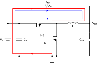 Figure 2-2 Steady State
Operation of Sinking Current
 Figure 2-3 and Figure 2-4 show simulation circuits of a synchronous buck converter (ideal open-loop) with sourcing current and sinking current. Figure 2-5 and Figure 2-6 show their steady state waveforms. Both converters regulate 12-V input to 5-V 1-A output with the same components value but with a different load so that both load current equals 1 A. The real-time simulation shows both converters have the same duty cycle (for example 41.67%) which conforms to the output-input relation (VOUT = D × VIN) of a buck converter.
It also can be seen from Figure 2-5 and Figure 2-6 that all waveforms, except for the input capacitor waveform, are symmetrical to each other. The differences in input capacitor waveform are due to load difference. The load power in Figure 2-3 is 7 W, which requires a larger input capacitor to supply the higher switching current demanded when the MOSFET turns on than the load power in Figure 2-4 which is 5 W for the same input ripple requirement.
In conclusion, for the same input and output conditions, sourcing current use and sinking current use of synchronous buck converter have the same power stage (except for the input capacitor), as well as the same design methods and formulas.
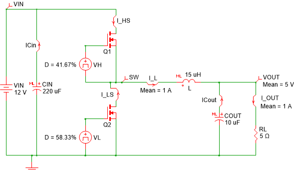 Figure 2-3 Synchronous Buck
Sourcing Current Simulation
 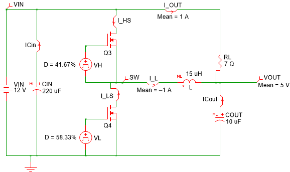 Figure 2-4 Synchronous Buck
Sinking Current Simulation
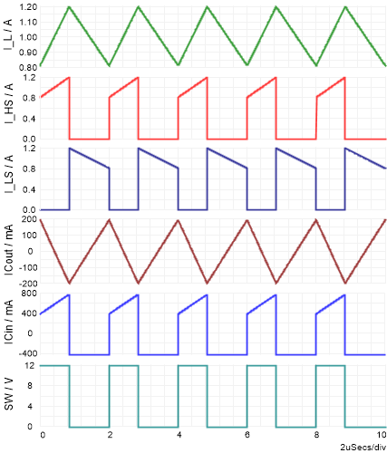 Figure 2-5 Steady State Waveforms
Sourcing Current
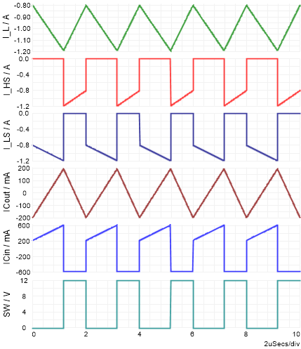 Figure 2-6 Steady State Waveforms
Sinking Current