SLUAAB9A March 2021 – December 2021 UCC25800-Q1
- Trademarks
- 1 Introduction
- 2 Open-Loop LLC Converter Operation Principle
- 3 Primary-side and Secondary-side Resonant Configurations
- 4 Rectification Methods
- 5 LLC Transformer Design Steps
- 6 Negative Voltage Generation
- 7 Multiple-output Design
- 8 EMI Performance
- 9 Common-Mode Transient Immunity (CMTI)
- 10Summary
- 11Revision History
6.1 Using a Zener Diode
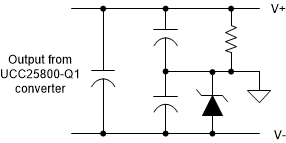
The output voltage can be split using a simple Zener diode if the voltage regulation requirement is not stringent. The method is shown in Figure 6-1.
 |
|
| (a) Regulated negative voltage | (b) Regulated positive voltage |
In the example of regulated negative voltage, the negative output voltage is determined by the Zener diode. The remaining voltage is left to be the positive voltage. In this case, the resistor is needed to provide the bias current for the Zener diode. The positive output and negative output capacitors can be designed to be proportional to its corresponding voltage. In this case, the two output voltages would rise proportionally. Otherwise, the Zener diode side could reach its final value much earlier than the positive side. The Zener diode can also be put on the positive side so that the positive voltage is determined by the Zener diode and the negative voltage is the rest of the voltage.