SLUAAG7 October 2021 BQ25720
- Trademarks
- 1Introduction
-
2Design Considerations for Notebook
Applications
- 2.1 Vmin Active Protection (VAP)
- 2.2 Fast Role Swap (FRS)
- 2.3 Processor Hot Indication
- 2.4 Two-Level Battery Discharge Current Limit
- 2.5 Pass Through Mode (PTM) Operation
- 2.6 Seamless Mode Transition
- 2.7 Current and Power Monitor
- 2.8 Input Source Dynamic Power Management
- 2.9 Power Up USB Port From Battery (USB OTG)
- 3Test Results
- 4Summary
- 5References
3 Test Results
The following are the results tested using BQ25720EVM with a 2-cells battery.
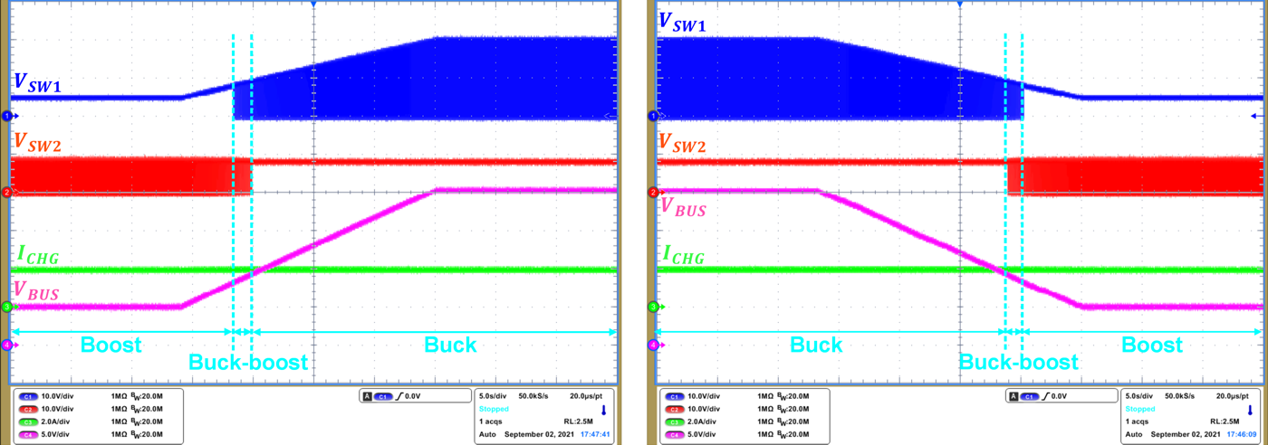
In Figure 3-1 (left), when charge current is set to 1A and VBUS voltage increases from 5 V to 20 V, the operating modes transition from boost to buck-boost, then to buck mode. The charging current is always kept at 1A regardless of VBUS.
In Figure 3-1 (right), when charge current is set to 1A and VBUS voltage decreases from 20 V to 5 V, and operating modes transition from buck to buck-boost, then to boost mode. The charging current is always kept at 1A regardless of VBUS.
 Figure 3-1 Seamless Transition Among
Different Operation Modes
Figure 3-1 Seamless Transition Among
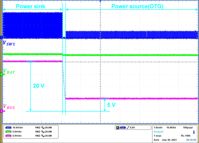
Different Operation ModesFigure 3-2 shows FRS transition waveform, which ensures that the power role swapping occurs in a timely manner to avoid experiencing momentary power loss or glitching.
 Figure 3-2 FRS Transition From Power Sink
to Power Source