SLUAAJ6 april 2023 BQ25171-Q1 , BQ51013B-Q1
2.2 Linear Charger (BQ25171-Q1)
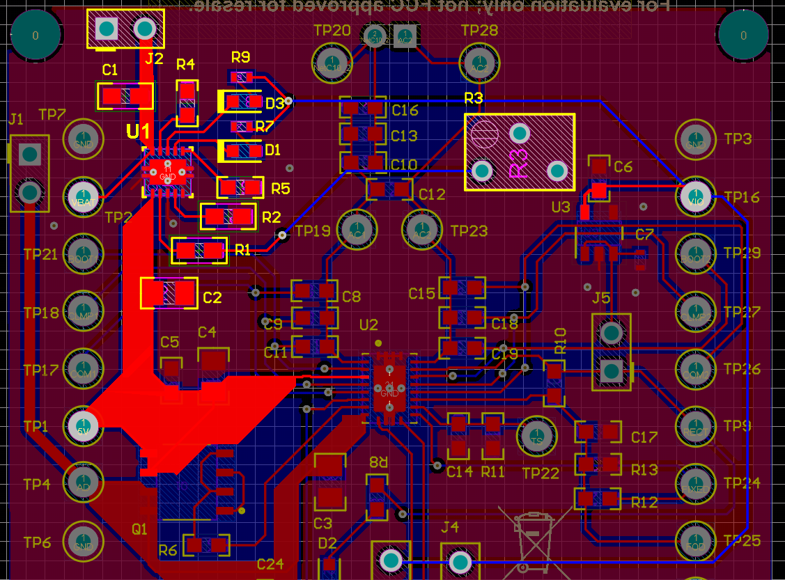
To obtain optimal performance, the decoupling capacitor from IN to GND and the output filter capacitor from OUT to GND should be placed as close as possible to the device, with short trace runs to both IN, OUT and GND.
- All low-current GND connections should be kept separate from the high-current charge or discharge paths from the battery. Use a single-point ground technique incorporating both the small signal ground path and the power ground path.
- The high current charge paths into IN pin and from the OUT pin must be sized appropriately for the maximum charge current to avoid voltage drops in these traces.
 Figure 2-2 Layout of BQ25171-Q1