SLUAAR2 august 2023 BQ27Z746
1 Introduction
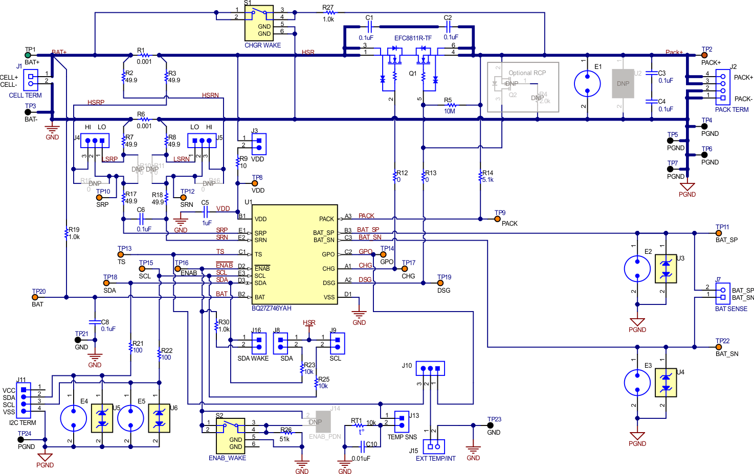
The BQ27Z746 EVM schematic is shown in Figure 1-1. The BQ27Z746 EVM includes a reverse charge circuit as Optional RCP consisting of Q2 FET and R4 gate resistor. The purpose of this circuit is to hold the gate of the discharge FET at the source potential to keep it off when the PACK+ terminal is pulled below VSS. This circuit will be important if an IC does not have internal RCP feature when a system uses a common connector such as a coaxial power connector for the charger. Since adapters with both polarities are available in the market, the incorrect charger could be attached and experience a reverse voltage condition.
 Figure 1-1 BQ27Z746 EVM Schematic
With a reversed charger, both the battery and charger will push current to flow in the same direction. The result can be a short circuit, or discharge to undervoltage with a protection event in battery. Therefore, most cell manufacturers specify that the battery pack must be protected from reverse charging connection. Figure 1-2 shows an example of specification from usual cell manufacturer as part.
 Figure 1-2 Example of Specification for RCP
When the protector attempts to turn off, it drives DSG to 0 V. If the charger has survived the event, the voltage goes negative. As the PACK+ terminal and source of discharge FET are forced to a negative voltage by the reversed charger, the DSG pin remains at approximately 0 V. The discharge FET is then conducted as a source follower since there is a positive voltage across gate to source of discharge FET. It operates in the ohmic region which can cause heating of the FET and failure, thus causing a short circuit event, draining the battery. Discharge FET can be damaged and burned out if the current is too high which is not safe. Figure 1-3 shows an example of current flow with a reversed charger when there is no RCP feature. BQ27Z746 has an internal RCP feature, so it depends on system needs to use optional RCP circuit or not. See Section 2 and Section 3 for more details about both cases.
 Figure 1-3 Currents with Reversed Charger Connection