SLUAAW2 July 2024 UCC25800-Q1 , UCC2803-Q1
3 11KW OBC Auxiliary Power Supply Power Requirement
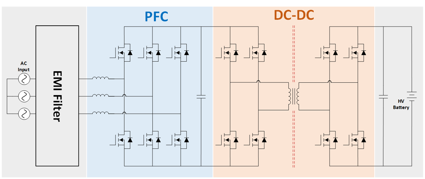
At present, OBC is developing in the direction of high power. 11KW OBC is the current mainstream power range. It is of great significance to design a low-cost, high-performance OBC auxiliary power supply. Figure 3-1 shows the architecture of a three-phase 11KW OBC.
 Figure 3-1 Three-Phase 11KW OBC
Architecture
Figure 3-1 Three-Phase 11KW OBC
ArchitectureFor the PFC side, assume that the driving power required by each SiC is Pbias=0.8W,For the DC-DC side, assume that the driving power required by each SiC is Pbias=1.4W. Table 3-1 shows the power requirements of the three-phase 11KW OBC. (The data are only estimated data based on the general OBC architecture, and designers can adjust them according to their actual needs.)
| Item | Quantity | Power (W) |
|---|---|---|
| PFC driving power (SiC) | 6 | 0.8*6 = 4.8 |
| AC Voltage Sensing | 4 | 0.05*4 = 0.2 |
| AC Current Sensing | 4 | 0.05*4 = 0.2 |
| DC-DC driving power (SiC) | 8 | 1.4*8 = 11.2 |
| DC Voltage Sensing | 1 | 0.05*1 = 0.05 |
| DC Current Sensing | 2 | 0.05*2 = 0.1 |
| MCU | 1 | 1 |
| Total power | 17.55(W) |