SLUAAW2 July 2024 UCC25800-Q1 , UCC2803-Q1
4 Low-Cost, High-Performance Auxiliary Power Solution
The LLC converter has high efficiency. TI's UCC25800-Q1 transformer driver is open-loop control, so it is necessary to add a pre-voltage pre-regulator between the low-voltage 12V battery and the auxiliary power circuit to make the UCC25800-Q1 work at a fixed input voltage, commonly used pre-voltage pre-regulator circuits are Boost or Sepic circuits. The research scope of this article is to use a low-voltage 12V battery as the input. Considering the fluctuation of the input voltage range, the input voltage range is generally 6-18V. The Sepic circuit is suitable for occasions where there is a need for Boost and Buck. Compared with the Boost converter, the Sepic converter has an additional energy storage inductor and a DC blocking capacitor. The system BOM cost is higher and the design is more complex. The input voltage range of UCC25800-Q1 is 9-34V. Under the condition of 34V input voltage, the power of UCC25800-Q1 can up to 9W. This solution selects UCC2803-Q1 as the Boost converter to increase the 12V voltage of the low-voltage battery to 34V as the front-stage voltage pre-regulator.
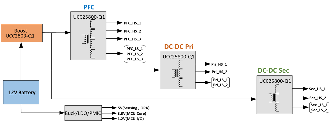
The block diagram of this solution is shown in Figure 4-1. The peripheral circuit design of this solution is simple, the efficiency can reach 85%-90%, and the output voltage adjustment accuracy can reach ±5%.
 Figure 4-1 Boost+LLC Block
Diagram
Figure 4-1 Boost+LLC Block
DiagramThe system BOM cost of this solution is shown in Table 4-1.
| Part Group | Description | Qty | Device Cost [$] | Cost [$] |
|---|---|---|---|---|
| LLC | UCC25800-Q1 | 3 | 0.28 | 0.84 |
| Boost | UCC2803-Q1 | 1 | 0.18 | 0.18 |
| Buck/LDO/PMIC | 1 | |||
| Capacitor large | 1206 | 5 | 0.05 | 0.25 |
| Capacitor medium | 805 | 36 | 0.03 | 1.08 |
| Capacitor small | 603 | 6 | 0.01 | 0.06 |
| Resistor | 603 | 21 | 0.002 | 0.042 |
| Mosfet | 1 | 0.5 | 0.5 | |
| Diode | 28 | 0.03 | 0.84 | |
| Transformer | 3 | 0.5 | 1.5 | |
| 104 | 6.29 |
The pros and cons of this solution are shown in Table 4-2.
| Item | Performance |
|---|---|
| Total system cost | Low |
| Efficiency | High |
| Component count | Medium |
| EMI | High |
| Regulation accuracy | Low |
| Power density | Medium |
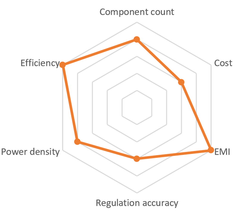
The radar chart is shown in Figure 4-2.
 Figure 4-2 Boost+LLC Radar
Diagram