SLUAAY1 October 2024 UCC28064A
- 1
- Abstract
- Trademarks
- 1Introduction
- 2Interleaving PFC Principle of Operation
- 3Original PFC Design with Internal Line Feed-Forward block
- 4Current Phenomenon of Operating With UCC28064A Internal Line Feed Forward Function
- 5Achieving Adaptive Current Control PFC With UCC28064A
- 6Test Results Comparing Original PFC Design to Adaptive PFC Design
- 7Summary
- 8References
6 Test Results Comparing Original PFC Design to Adaptive PFC Design
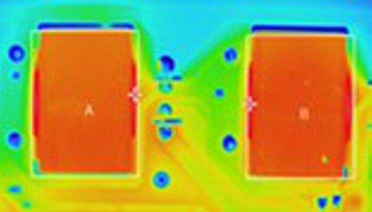
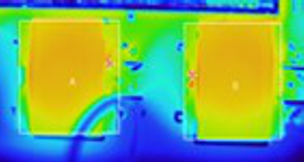
Table 6-1 shows thermal test result with decrease temperature in PFC block components, especially PFC inductor with applying adaptive PFC external circuit design against original boost PFC design.
| Original Interleaved PFC | Interleaved Adaptive PFC | Remark | |
|---|---|---|---|
| Inductor |
|
|
|
| EER3311 x 2EA | EER3311 x 2EA | ||
| 140μH, 0.1Φx30P | 140μH, 0.1Φx30P | ||
| 71.5. °C | 62.1°C | 10.4℃↓ | |
| FET | 56.8°C | 52.7°C | 4.1℃↓ |
| Diode | 56.5°C | 52.6°C | 3.9℃↓ |
Table 6-2 shows efficiency test result of increased efficiency value at total board condition when applying adaptive PFC external circuit design against original boost PFC design.
| Input Voltage | 110Vac | 230Vac |
|---|---|---|
| Load | Efficiency Improvement | Efficiency Improvement |
| 25% | 1.96% | 0.69% |
| 50% | 1.11% | 0.61% |
| 75% | 0.88% | 0.43% |
| 100% | 0.62% | 0.33% |
Table 6-3 shows PF(Power Factor) test result of decreased PF value at low AC input condition when applying adaptive PFC external circuit design against original boost PFC design. But the PF standard is 0.9 or higher and this standard is met even if an adaptive PFC design is applied.
| Input Voltage | Original PFC | Adaptive PFC |
|---|---|---|
| 90Vac | 0.99 | 0.95 |
| 132Vac | 0.99 | 0.95 |
| 230Vac | 0.95 | 0.95 |
| 264Vac | 0.94 | 0.94 |
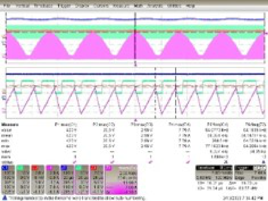
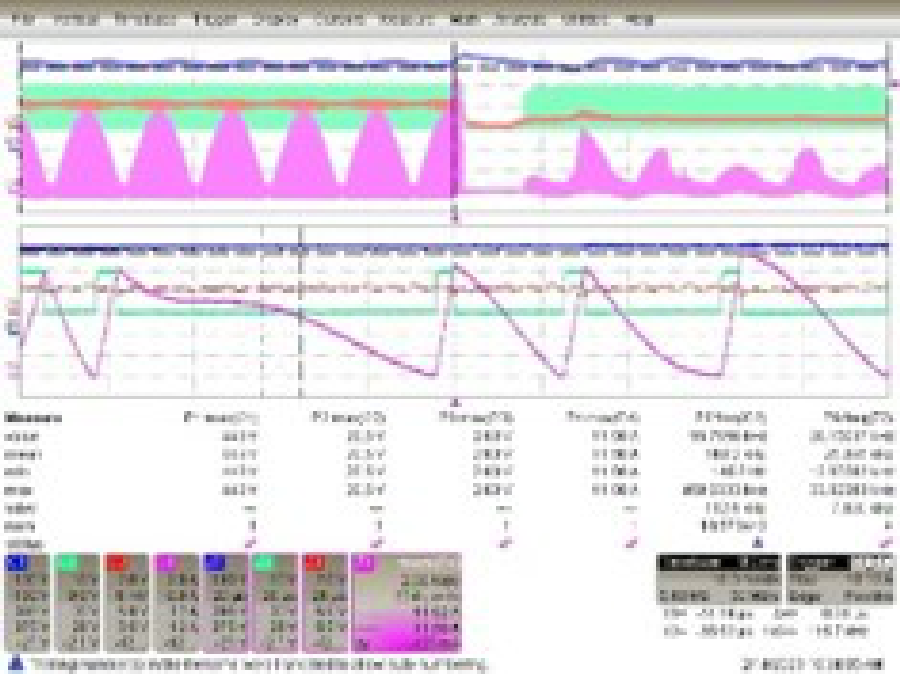
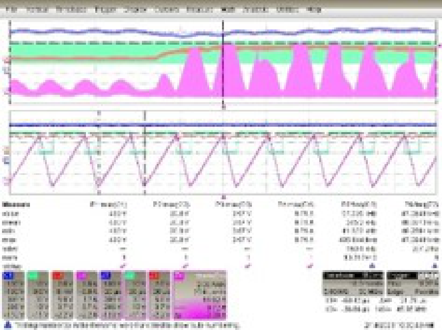
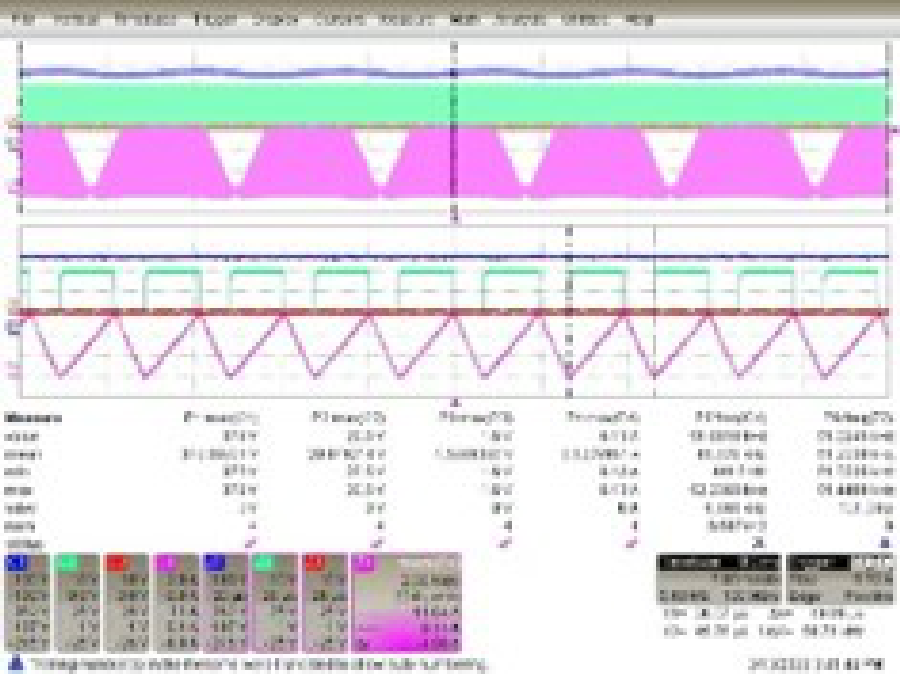
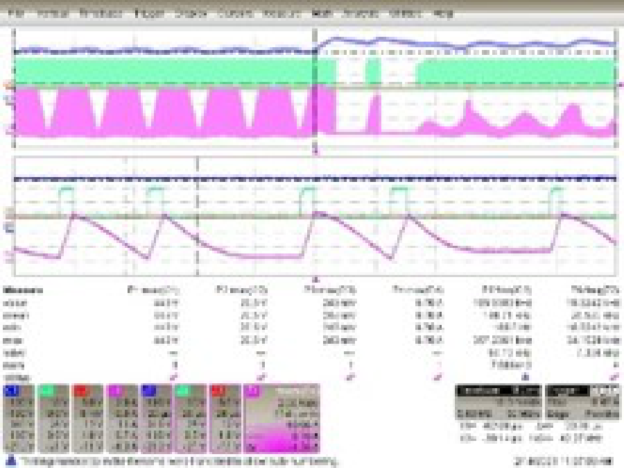
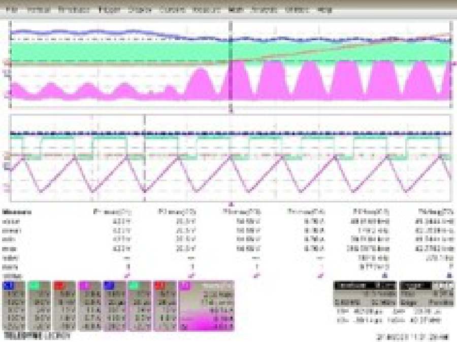
Table 6-4 shows various comparison waveforms especially inductor current value with applying adaptive PFC external circuit design against original boost PFC design. As shown from the comparison waveforms, the board with adaptive PFC external circuitry has a significantly lower inductor current value than the existing circuit board.
| Original PFC | Adaptive PFC | |
|---|---|---|
|
Max Load Operating |
|
|
| ILmax = 7.79A(Vin:90Vac,Vout:395V) | ILmax = 6.13A(Vin:90Vac,Vout:353V) | |
|
Normal Operating |
|
|
| ILmax | ILmax = 7.09A(Vin:90Vac,Vout:395V) | ILmax = 5.62A(Vin:90Vac,Vout:353V) |
|
Line Transient Operating (264Vac to 90Vac) |
|
|
| ILmax | ILmax = 9.71A | ILmax = 6.70A |