SLUAAY7 November 2024 BQ25756
2.1 Equipment Setup
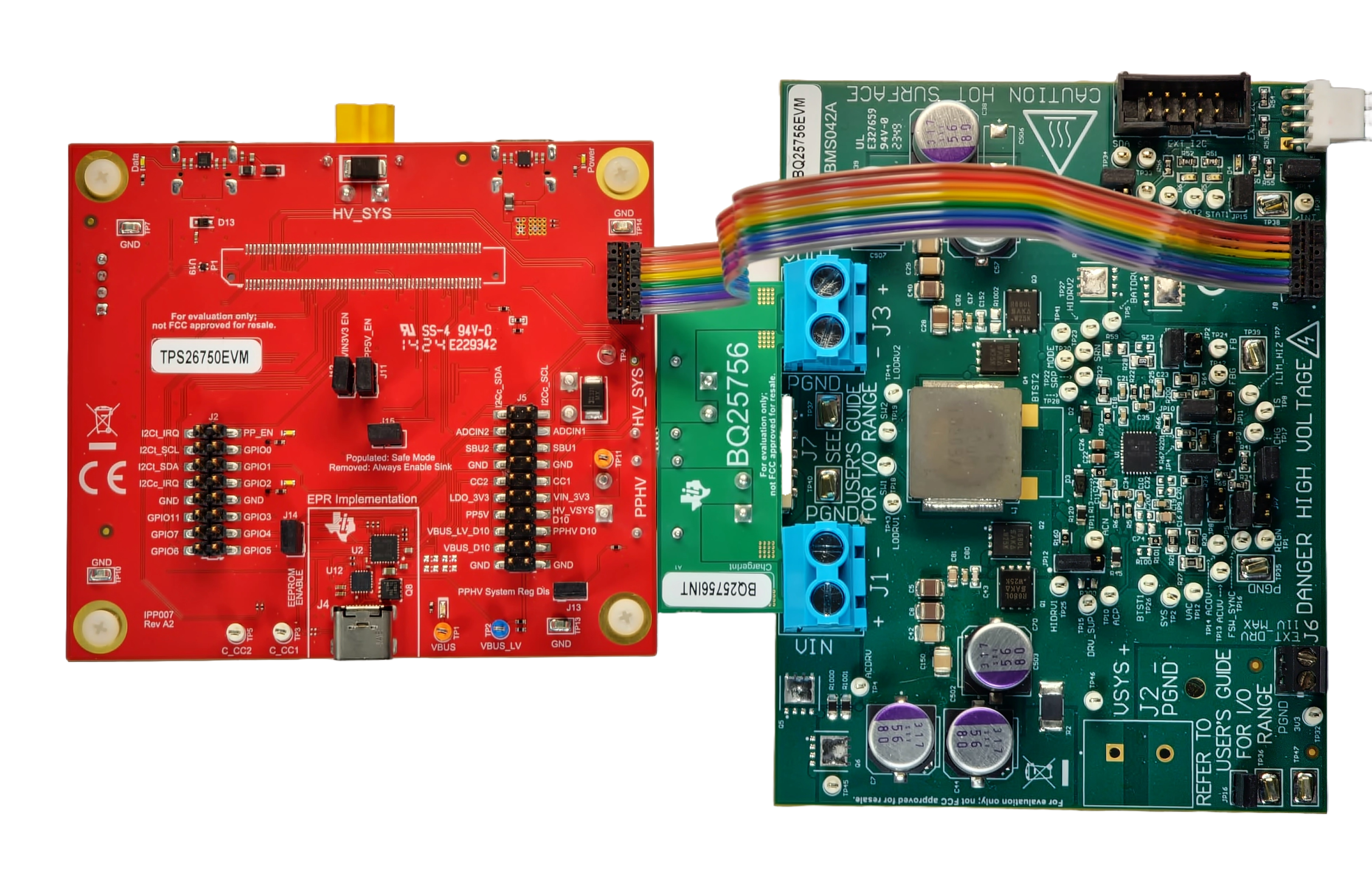
 Figure 2-1 TPS26750EVM and BQ25756EVM
Hardware Setup
Figure 2-1 TPS26750EVM and BQ25756EVM
Hardware SetupUse the following guidelines to set up the EVMs:
- Follow the TPS26750EVM User
Guide and TPS26750
Web Application to configure one of the TPS26750 EVM as a sink device
and the other TPS26750EVM as a source device.Note: The BQ25756EVM has a default charge voltage of 29.4V. In order to see the full EPR range, the voltage divider on the BQ25756 FB pin needs to be changed to support a higher charger voltage or the charge current needs to be increased to 8A. The power supply on the source side is fed from the J8 connector of TPS26750 into the battery terminal of BQ25756. The voltage on the power supply needs to be proportional to the charge voltage programmed using the voltage divider on the BQ25756 FB pin. The load voltage should be set slightly lower than the targeted charge voltage (to simulate a battery that is not fully charged yet). Since the default charge voltage is 29.4V, the recommend power supply should be 29.4V with a current limit of 9A, and the load voltage should be 28V with a current limit of 9A.
- Connect the J1 and J7 mating connectors of the TPS26750EVM to the reciprocal connectors on the provided BQ25756 interposer board.
- Insert the other side of the BQ25756 interposer board to headers J1 and J3 on the BQ25756EVM. Make sure the prongs are inserted all the way into the headers.
- Attach one end of the ribbon cable to header J9 on the TPS26750EVM, attach the other end of the ribbon cable to header J8 of the BQ25756EVM.
- Install the jumpers as indicated in IO and Jumper Descriptions of the BQ25756EVM User Guide.
- Repeat steps 1-5 for the other set of EVMs
- There
should be two combination of EVMs, one should be configured as the sink device
and the other should be configured as a source device.
- On the source side, connect the power supply to port J8 of the TPS26750EVM. and set the power supply voltage to 29.4V with a current limit of 9A
- On the sink side, connect the load to port J8 of the TPS26750EVM and set the load voltage to 28V with a current limit of 9A
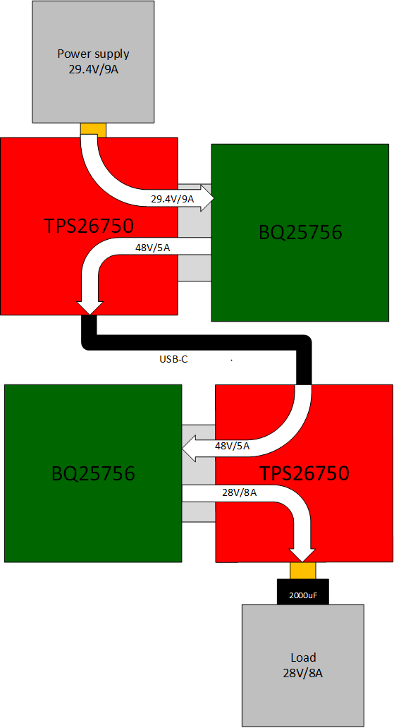
 Figure 2-2 Block Diagram of the
Source side connected to the Sink side
Figure 2-2 Block Diagram of the
Source side connected to the Sink sideOn the source side, the power supply is connected to port J8 of the TPS26750EVM. The power supply voltage is set to 29.4V with a current limit of 9A. On the sink side, the load is connected to port J8 of the TPS26750EVM. The load voltage is set to 28V with a current limit of 9A. The white arrows shows how the power from the power supply is transferred to the load supply.