SLUAB02 November 2024 BQ25173-Q1 , BQ25856-Q1
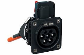
Emerging electric vehicle (EV) drivetrains are shaking up the way cars are built, but how do EVs affect the design of other components besides the powertrain? Many EVs are adding backup power systems in the charging inlet and microcontroller unit (MCU) farm systems for emergency power when the main car battery is unavailable. As shown in Figure 1, the charging inlet is the port where the charging cable is inserted into the EV, and within the charging inlet, a motor clamps the charging cable to the EV to verify a secure connection during charging. A backup power system for the motor is required for North American Charging Standard (NACS) charging inlets because the charging inlets are ASIL-D rated. MCU farms are the brains of the vehicles controlling systems like airbags, emergency braking and sensors. Having the backup power for these critical systems in case the car battery gets disconnected is necessary. Although NACS charging inlets and MCU farms have different functionality, both are critical for driver safety and utilize supercapacitors for backup power due to the quick rechargeability. To design these supercapacitor backup systems, engineers face the challenges of quick charging while managing power loss, accurate charging to utilize the supercapacitors’ full capacity and boosting the supercapacitors quickly to support the backup functionality.
 Figure 1 EV Charging Inlet
Choosing the right charger topology based on application specifications
Supercapacitors must be charged quickly to make sure backup power is available soon after the car turns on, but how does one choose the right charger topology based on the system requirements? Equation 1 relates the voltage and charge time which helps select the right charger topology for charging inlets and MCU farms. In Equation 1, I is the charge current, C is total capacitance, dV is the supercapacitor voltage and dT is the charge time.
Typically, MCU farms have a higher charge voltage of 48V compared to the 10V of charging inlets to provide backup power for a longer period of time and a shorter charge time of < 60 seconds. Therefore, the MCU farm application requires more charge current resulting in greater power loss compared to the charging inlet. To support higher power dissipation, a switching charge controller is an effective charger topology for the MCU farm. The switching behavior helps reduce heat due to power loss while the controller topology places the switching FETs external to the charger to improve power capability. The charging inlet application can use a linear charger since the power loss is smaller. Linear chargers also help reduce the total components since linear chargers do not require inductors and MOSFETs like a switching charge controller.
Help maximize the charge on the supercapacitors
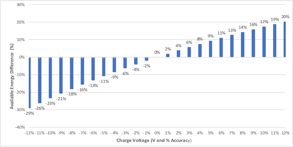
Another key challenge to address is charging the supercapacitors as close to the full charge as possible. All charging designs have a charge voltage accuracy specification that details how far above or below the actual charge voltage can be compared to the target charge voltage. Ambient temperature affects the charge voltage accuracy as well. Some ICs can have a 1% charge voltage accuracy at 25°C ambient temperature, but the accuracy can get worse at higher and lower ambient temperatures. Charge voltage accuracy is important to the charging inlet and MCU farm applications. The supercapacitors have less charge to use during backup mode if the actual charge voltage is less than expected. If the charge voltage is higher than expected, then the supercapacitor can be charged above what is rated, which can degrade the capacitor. Figure 2 highlights how the available energy in a supercapacitor increases or decreases exponentially with the charge voltage accuracy. Looking specifically at the 1% to 2% charge voltage accuracy range, the graph shows how a 1% change in charge voltage accuracy can double the energy overcharge or undercharge of the supercapacitors. Therefore, charge voltage accuracy must be considered when designing supercapacitor systems like charging inlets and MCU farms to maximize the available charge in the supercapacitors without sacrificing longevity.
 Figure 2 Available Energy Difference vs Charge Voltage
Boosting the supercapacitor voltage to power the system in backup mode
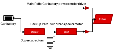
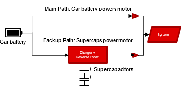
Another design challenge for supercapacitor systems is boosting to the supercapacitors’ voltage to a level high enough to power the system. For charging inlets, the supercapacitors are charged to a total of 10V while the motor driver to unlock the door typically needs 60W (10V, 6A), so a boost converter is needed to step up the power while the supercapacitors are discharging. Two ways to implement boosting are shown in the block diagrams below: charging and boosting on the same IC or charging and boosting on separate ICs. The block diagram is the same for MCU farms except the Motor Driver component is replaced by MCUs. The main benefit of the charger and boost combined is reducing the total number of components and simplifying system design.
 Figure 3 Charger and Boost Separate Block Diagram
 Figure 4 Charger and Boost Combined Block Diagram
BQ25173-Q1 and BQ25856-Q1 supercapacitor chargers
BQ25173-Q1 and BQ25856-Q1 are linear and switching supercapacitor chargers that can be used in automotive applications like charging inlets and MCU farms. BQ25173-Q1 can charge 1-4 supercapacitors in series and has the following benefits:
Minimize current draw from car battery and supercapacitors with 2uA input quiescent current and 350nA quiescent current
Charge supercapacitors to the target charge voltage with +-1% charge voltage accuracy from -40°C - 125°C ambient temperature
No electromagnetic interference (EMI) with linear charging topology
Achieve charge current > 1A and better thermal performance with parallel BQ25173-Q1s
BQ25173-Q1 needs to be paired with a boost IC like in the charger + boost separate block diagram. BQ25856-Q1 is an excellent choice for higher power charging applications like MCU farms and comes with the following benefits:
- Supports high input and output voltage applications with up to 70V tolerance on the input and output
- Capable of charging and boosting supercapacitors with forward and reverse power modes
- Quickly charge the supercapacitors with up to 20A of charge current in forward and reverse mode
- Help charge supercapacitors to the target charge voltage with +-0.5% charge voltage accuracy from -40°C - 125°C ambient temperature
The wide Vin range of the BQ25856-Q1 charge controller supports direct connection to 12V or 48V car batteries and the reverse boost mode function saves an additional boost converter IC while providing uninterrupted system power. BQ25173-Q1 and BQ25856-Q1 supercapacitor chargers help provide designs for low and high power supercapacitor backup applications.
Conclusion
Supercapacitor backup power is getting more popular as more systems in EVs are electrically driven, and charging inlets and MCU farms are two examples that require backup power. The BQ25173-Q1 and BQ25856-Q1 are two supercapacitor charger options that can be used in automotive backup applications. BQ25173-Q1 is a good option for EMI sensitive systems with linear topology and requires an external boost IC to discharge the supercapacitors. BQ25856-Q1 is a switching charge controller option for high power applications, and the reverse mode function can boost the supercapacitors to provide uninterrupted power to back up the system. BQ25173-Q1 and BQ25856-Q1 can help engineers design a variety supercapacitor backup systems for electrically powered car systems.