SLUP408 February 2022 LM25149-Q1 , LM61460-Q1 , LM61495-Q1 , LMQ61460-Q1
- 1 Introduction
- 2 Defining EMI
- 3 What Causes EMI in a Switched-Mode DC/DC Regulator?
- 4 Existing Passive EMI Filtering Techniques
- 5 Passive Filter Limitations
- 6 AEF
- 7 Spread Spectrum
- 8 DRSS
- 9 True Slew-Rate Control
- 10HotRod™ Package Technology
- 11Optimized Package and Pinout
- 12Integrated Capacitors
- 13Conclusions
- 14References
- 15Important Notice
11 Optimized Package and Pinout
Another benefit of HotRod package technology is the optimization of the input path pinouts. The input-high transient current (di/dt) loop is critical in a step-down converter; Figure 11-1 illustrates the importance of minimizing the area of this loop. HotRod package technology enables you to easily place and route the input decoupling capacitors close to the input and ground pins. The reduction in switching power-loop parasitic inductances and minimal input trace routing contribute to a lower EMI signature. Input pinout optimization also reduces switch-node ringing, output voltage noise and EMI.
 Figure 11-1 Input capacitor placement near
the converter IC (a) results in 7 dBµV less noise than placement farther away
(b).
Figure 11-1 Input capacitor placement near
the converter IC (a) results in 7 dBµV less noise than placement farther away
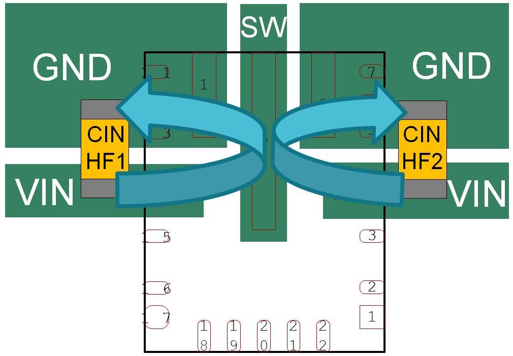
(b).Current flowing through a copper trace generates a magnetic field, which results in an overall increase in EMI noise measurements. The HotRod package pinout is designed to have the input current loop split onto either side of the device, as shown in Figure 11-2. This symmetrical input and ground pinout consideration in HotRod devices creates an equal and opposite magnetic field, which provides a self-containing effect on the magnetic field and further reduces EMI [5].
 Figure 11-2 Symmetrical HotRod package
pinout.