SLUP408 February 2022 LM25149-Q1 , LM61460-Q1 , LM61495-Q1 , LMQ61460-Q1
- 1 Introduction
- 2 Defining EMI
- 3 What Causes EMI in a Switched-Mode DC/DC Regulator?
- 4 Existing Passive EMI Filtering Techniques
- 5 Passive Filter Limitations
- 6 AEF
- 7 Spread Spectrum
- 8 DRSS
- 9 True Slew-Rate Control
- 10HotRod™ Package Technology
- 11Optimized Package and Pinout
- 12Integrated Capacitors
- 13Conclusions
- 14References
- 15Important Notice
10 HotRod™ Package Technology
TI’s buck-regulator portfolio provides a multitude of different package technologies that can help meet design expectations. The two most common package technologies available are standard wire-bond quad flat no-lead (QFN) and flip-chip-on-leadframe (the HotRod package). Packages optimized for EMI have reduced power-loop parasitic inductance, which reduces switch-node ringing.
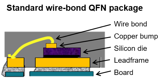
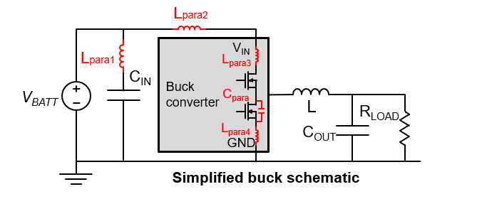
As shown in Figure 10-1, QFN packages connect the die to the leadframe through wire bonds. A design drawback of the QFN package device is the additional parasitic inductance resulting from the wire bond connecting the copper bump and silicon die to the leadframe. Figure 10-2 shows the internal parasitic inductance (Lpara3 and Lpara4) in the simplified buck schematic. The parasitic inductance resonates with the parasitic capacitance of the switch node at every switch edge, causing undamped switch ringing and thus the potential for EMI.
 Figure 10-1 A standard QFN package
construction.
 Figure 10-2 Typical buck converter input
parasitic elements.
Figure 10-2 Typical buck converter input
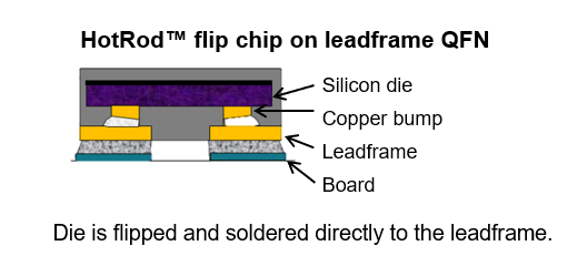
parasitic elements.The HotRod package, as shown in Figure 10-3, provides a lower-noise solution by eliminating the use of bond wires. HotRod packages significantly minimize parasitic inductance, since the copper bumps are in direct contact with the leadframe. Step-down converters such as the LM61460-Q1, LMQ61460-Q1 and LM61495-Q1 are available in HotRod packaging to help meet system EMI requirements.
 Figure 10-3 HotRod package
construction.