SLUS609J May 2004 – January 2018 TPS51116
PRODUCTION DATA.
- 1 Features
- 2 Applications
- 3 Description
- 4 Revision History
- 5 Pin Configuration and Functions
- 6 Specifications
-
7 Detailed Description
- 7.1 Overview
- 7.2 Functional Block Diagram
- 7.3
Feature Description
- 7.3.1 VDDQ SMPS, Light Load Condition
- 7.3.2 Low-Side Driver
- 7.3.3 High-Side Driver
- 7.3.4 Current Sensing Scheme
- 7.3.5 PWM Frequency and Adaptive On-Time Control
- 7.3.6 VDDQ Output Voltage Selection
- 7.3.7 VTT Linear Regulator and VTTREF
- 7.3.8 Controling Outputs Using the S3 and S5 Pins
- 7.3.9 Soft-Start Function and Powergood Status
- 7.3.10 VDDQ and VTT Discharge Control
- 7.3.11 Current Protection for VDDQ
- 7.3.12 Current Protection for VTT
- 7.3.13 Overvoltage and Undervoltage Protection for VDDQ
- 7.3.14 Undervoltage Lockout (UVLO) Protection, V5IN (PWP), V5FILT (RGE)
- 7.3.15 Input Capacitor, V5IN (PWP), V5FILT (RGE)
- 7.3.16 Thermal Shutdown
- 7.4 Device Functional Modes
- 8 Application and Implementation
- 9 Power Supply Recommendations
- 10Layout
- 11Device and Documentation Support
- 12Mechanical, Packaging, and Orderable Information
6.7 Typical Characteristics
All data in the following graphs are measured from the PWP packaged device.
| DDR2 | VVTT = 0.3 V |

Figure 5. CS Current vs Junction Temperature

Figure 7. VTT Discharge Current vs Junction Temperature

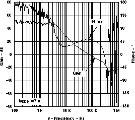
| DCAP Mode | IVDDQ = 7 A |

| DDR | VIN = 12 V |
| DCAP Mode |

| DDR |

| DDR3 | VVLDOIN = 1. 5 V |

| DDR | D021 |

| DDR3 |

| DDR | VVDDQ = 2.5 V |
| fSW = 400 kHz |

| Heavy Load |

Figure 25. VTT Load Transient Response

Figure 27. Soft-Start Waveforms Tracking Discharge

| Current mode |

| DDR2 | Sink |

Figure 2. V5IN Shutdown Current vs Junction Temperature

Figure 4. VLDOIN Supply Current vs Junction Temperature

Figure 6. VDDQ Discharge Current vs Junction Temperature

Figure 8. Overvoltage and Undervoltage Threshold vs Junction Temperature

| DCAP Mode | VIN =12 V |

| DDR2 | DCAP Mode |

| DDR2 |

| DDR4 |

| DDR2 |

| DDR4 |

| DDR2 | VVDDQ = 1.8 V |
| fSW = 400 kHz |

Figure 24. VDDQ Load Transient Response

Figure 26. VDDQ, VTT, and VTTREF Start-Up Waveforms

Figure 28. Soft-Stop Waveforms Non-Tracking Discharge

| DDR2 | Source |
