SLUS812D February   2008  – February 2020 TPS51200

PRODUCTION DATA.  

  1. Features
  2. Applications
  3. Description
    1.     Device Images
      1.      Simplified DDR Application
  4. Revision History
  5. Pin Configuration and Functions
    1.     Pin Functions
  6. Specifications
    1. 6.1 Absolute Maximum Ratings
    2. 6.2 ESD Ratings
    3. 6.3 Recommended Operating Conditions
    4. 6.4 Thermal Information
    5. 6.5 Electrical Characteristics
    6. 6.6 Typical Characteristics
  7. Detailed Description
    1. 7.1 Overview
    2. 7.2 Functional Block Diagram
    3. 7.3 Feature Description
      1. 7.3.1  Sink and Source Regulator (VO Pin)
      2. 7.3.2  Reference Input (REFIN Pin)
      3. 7.3.3  Reference Output (REFOUT Pin)
      4. 7.3.4  Soft-Start Sequencing
      5. 7.3.5  Enable Control (EN Pin)
      6. 7.3.6  Powergood Function (PGOOD Pin)
      7. 7.3.7  Current Protection (VO Pin)
      8. 7.3.8  UVLO Protection (VIN Pin)
      9. 7.3.9  Thermal Shutdown
      10. 7.3.10 Tracking Start-up and Shutdown
      11. 7.3.11 Output Tolerance Consideration for VTT DIMM Applications
      12. 7.3.12 REFOUT (VREF) Consideration for DDR2 Applications
    4. 7.4 Device Functional Modes
      1. 7.4.1 Low Input Voltage Applications
      2. 7.4.2 S3 and Pseudo-S5 Support
  8. Application and Implementation
    1. 8.1 Application Information
    2. 8.2 Typical Application
      1. 8.2.1 Design Requirements
      2. 8.2.2 Detailed Design Procedure
        1. 8.2.2.1 Input Voltage Capacitor
        2. 8.2.2.2 VLDO Input Capacitor
        3. 8.2.2.3 Output Capacitor
      3. 8.2.3 Application Curves
    3. 8.3 System Examples
      1. 8.3.1 3.3-VIN, DDR2 Configuration
      2. 8.3.2 2.5-VIN, DDR3 Configuration
      3. 8.3.3 3.3-VIN, LP DDR3 or DDR4 Configuration
      4. 8.3.4 3.3-VIN, DDR3 Tracking Configuration
      5. 8.3.5 3.3-VIN, LDO Configuration
      6. 8.3.6 3.3-VIN, DDR3 Configuration with LFP
  9. Power Supply Recommendations
  10. 10Layout
    1. 10.1 Layout Guidelines
    2. 10.2 Layout Example
    3. 10.3 Thermal Design Considerations
  11. 11Device and Documentation Support
    1. 11.1 Device Support
      1. 11.1.1 Third-Party Products Disclaimer
      2. 11.1.2 Development Support
        1. 11.1.2.1 Evaluation Modules
        2. 11.1.2.2 Spice Models
    2. 11.2 Documentation Support
      1. 11.2.1 Related Documentation
    3. 11.3 Community Resources
    4. 11.4 Trademarks
    5. 11.5 Electrostatic Discharge Caution
    6. 11.6 Glossary
  12. 12Mechanical, Packaging, and Orderable Information

3.3-VIN, DDR2 Configuration

This section describes a 3.3-VIN, DDR2 configuration application.
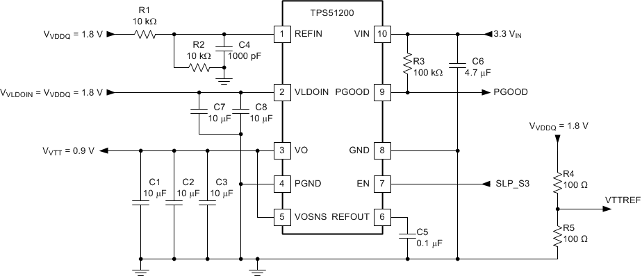
TPS51200 application_DDR2_tps51200.gifFigure 28. 3.3-VIN, DDR2 Configuration

Table 3. 3.3-VIN, DDR2 Configuration List of Materials

REFERENCE DESIGNATOR DESCRIPTION SPECIFICATION PART NUMBER MANUFACTURER
R1, R2 Resistor 10 kΩ
R3 100 kΩ
R4, R5 100 Ω
C1, C2, C3 Capacitor 10 μF, 6.3 V GRM21BR70J106KE76L Murata
C4 1000 pF
C5 0.1 μF
C6 4.7 μF, 6.3 V GRM21BR60J475KA11L Murata
C7, C8 10 μF, 6.3 V GRM21BR70J106KE76L Murata