SLUS846D September 2008 – August 2024 UCC25600
PRODUCTION DATA
- 1
- 1 Features
- 2 Applications
- 3 Description
- 4 Revision History
- 5 Pin Configuration and Functions
- 6 Specifications
- 7 Detailed Description
- 8 Application and Implementation
- 9 Power Supply Recommendations
- 10Layout
- 11Device and Documentation Support
- 12Glossary
- 13Mechanical, Packaging, and Orderable Information
8.1.1 Principal of Operation
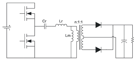
The soft-switching capability, high efficiency, and long holdup time make the LLC resonant converter attractive for many applications, such as digital TV, ac-to-dc adapters, and computer power supplies. Figure 8-1 shows the schematic of the LLC resonant converter.
 Figure 8-1 LLC
Resonant Converter
Figure 8-1 LLC
Resonant ConverterThe LLC resonant converter is based on the series resonant converter (SRC). By using the transformer magnetizing inductor, zero-voltage switching can be achieved over a wide range of input voltage and load. As a result of multiple resonances, zero-voltage switching can be maintained even when the switching frequency is higher or lower than resonant frequency. This simplifies the converter design to avoid the zero-current switching region which can lead to system damage. The converter achieves the best efficiency when operated close to its resonant frequency at a nominal input voltage. As the switching frequency is lowered, the voltage gain is significantly increased. This allows the converter to maintain regulation when the input voltage falls low. These features make the converter ideally suited to operate from the output of a high-voltage, boost PFC pre-regulator, allowing it to hold up through brief periods of ac line-voltage dropout.
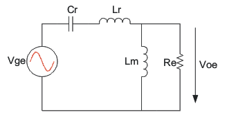
Due to the nature of resonant converter, all the voltages and currents on the resonant components are approximately sinusoidal. The gain characteristic of the LLC resonant converter is analyzed based on the first harmonic approximation (FHA), which means all the voltages and currents are treated as a sinusoidal shape with the frequency the same as the switching frequency.
According to the operation principle of the converter, the LLC resonant converter can be drawn as the equivalent circuit shown in Figure 8-2.
 Figure 8-2 LLC
Resonant Converter Equivalent Circuit