SLUU070A December   2001  – June 2021 TPS62100 , TPS62101 , TPS62102 , TPS62103


  1.   Trademarks
  2. 1Features
  3. 2Description
  4. 3Feedback Considerations
    1. 3.1 Error Amplifier
    2. 3.2 Open-Loop Small Signal AC Model
      1. 3.2.1 Open-Loop Small Signal AC Model
  5. 4Operating Instructions
    1. 4.1 Connect a DC Power Supply to Terminal TB1
    2. 4.2 Connect the Load to TB2
    3. 4.3 Place a Jumper on CB2
      1. 4.3.1 Placing a Jumper on CB1 is Optional
    4. 4.4 Turn on the Electronic Load
    5. 4.5 Turn on the Input Power Supply
    6. 4.6 Shut Down the Converter
  6. 5Evaluation Module Layouts
  7. 6Evalulation Module Components
  8. 7References
  9. 8Revision History

Evaluation Module Layouts

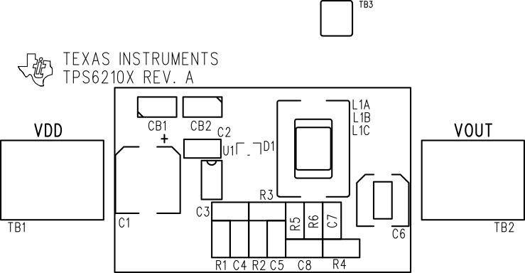
Evaluation module layout examples of the TPS62102EVM–01 PCB are shown in Figure 5-1 through Figure 5-3. They are not to scale and appear here only as a reference.
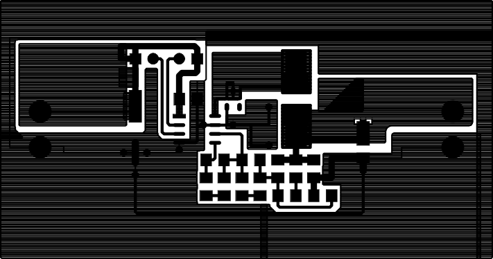
GUID-20210615-CA0I-4KKF-9FQB-NWHTQ5B3MN2V-low.gif Figure 5-1 Top Layer (Top View)
GUID-20210615-CA0I-XBCG-BJ3B-PQ4CJRNXSHQK-low.gif Figure 5-2 Bottom Layer (Top View)
GUID-20210615-CA0I-JRNQ-VVDZ-D0RGTTG1ZNVQ-low.gif Figure 5-3 Assenmbly Drawing (Top Assembly)