SLUUAV7C December 2013 – November 2022 BQ40Z50 , BQ40Z50-R2
- Abstract
- Trademarks
- 1Features
- 2bq40z50EVM Quick Start Guide
- 3Battery Management Studio
- 4bq40z50EVM Circuit Module Schematic
- 5Circuit Module Physical Layouts
- 6Bill of Materials
- 7Related Documentation from Texas Instruments
- 8Revision History
4.4 Testing Fuse-Blowing Circuit
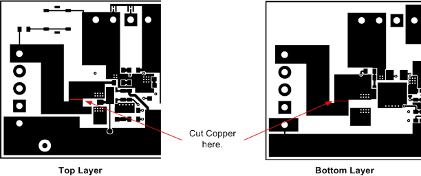
To prevent the loss of board functionality during the fuse-blowing test, the actual chemical fuse is not provided on the EVM. FET Q5 drives the FUSE test point low if a fuse-blow condition occurs. FUSE is attached to an open drain FET, so a pull-up resistor is required to check whether the FUSE pulls low. A FUSEPIN test point is attached to the gate of Q5; so, monitoring FUSEPIN can be used to test this condition without adding a pull-up resistor. Fuse placement on the application board is shown in the bq40z50 data sheet. A chemical fuse can also be soldered to the EVM for in-system testing. A copper bridge is included on the PCB to bypass the chemical fuse, so it has to be cut to allow the fuse to open the power path. The cut is illustrated in yellow on Figure 4-1 with arrows pointing to the location.
 Figure 4-1 Fuse Trace Modifications