SLUUBX7A August 2018 – January 2024 TPS560430-Q1
2.1 Input/Output Connector Description
VIN — Terminal TP1 – is the power input terminal for the converter. Adjacent is the GND reference ground. Use this terminal to attach the EVM to a cable harness.
VOUT — Terminal TP2 – is the regulated output voltage for the converter. Adjacent is the GND reference ground.
GND — Terminal TP4, TP5 – are the ground reference for the converter. Use these terminals to attach the EVM to a cable harness.
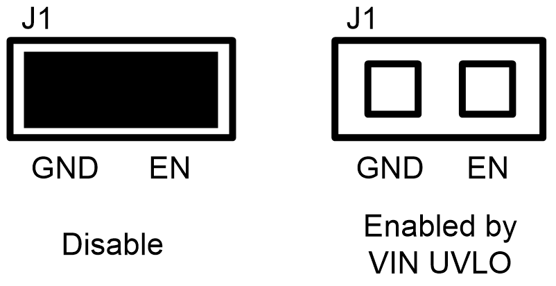
EN — Jumper J1 – is used to enable the switch-mode converter. The device is enabled when the EN pin is high, and disabled when low. EN turn off trip point also can be programmed by changing R1 or R2. Refer to TPS560430-Q1 data sheet for enable and adjustable under-voltage lockout.
 Figure 2-1 Enable Jumper Setting
Test Point — TP3, TP6, TP7 – these are test points used for loop response measurements.