SLUUC04A February 2019 – June 2021 TPS568230
5.1 Headers Description and Jumper Placement.
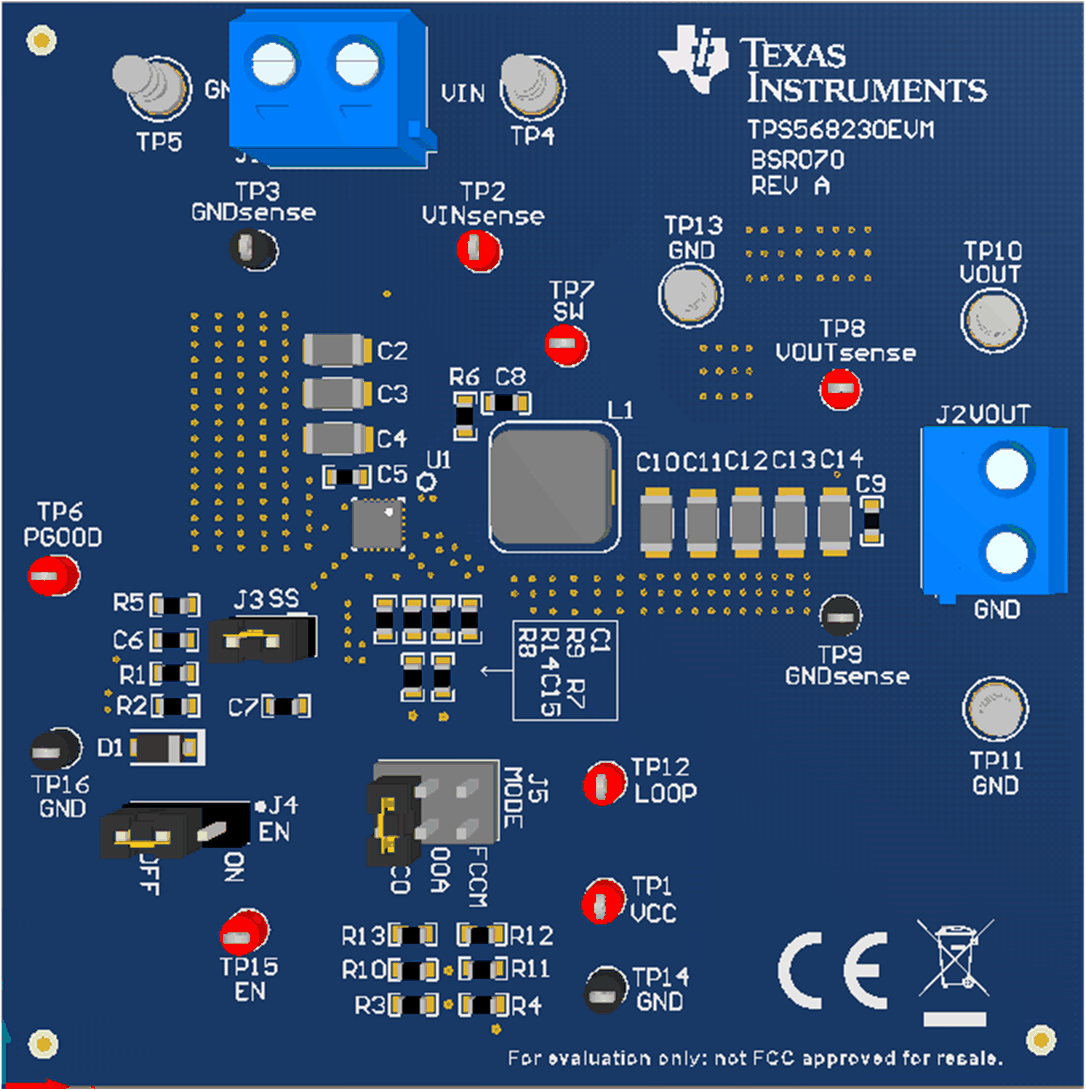
The TPS568230EVM header description is as Figure 5-1. A power supply capable of supplying greater than 4 A must be connected to J1 through a pair of 20-AWG wires or better. The load must be connected to J2 through a pair of 20-AWG wires or better. The maximum load current capability is 8 A. Wire lengths must be minimized to reduce losses in the wires. Test point TP2 provides a place to monitor the VIN input voltages with TP3 providing a convenient ground reference. TP8 is used to monitor the output voltage with TP9 as the ground reference.
 Figure 5-1 Headers Description and Jumper Placement
Connector and test point description is as Table 5-1.
Table 5-1 Input and Output Connection
| # | FUNCTION | DESCRIPTION |
|---|---|---|
| J1 | VIN connector | VIN power |
| J2 | VOUT connector | VOUT power |
| J3 | Internal/external Soft Start selection | When short J3, IC uses external SS by charging the cap C6. When float J3, IC uses internal SS. |
| J4 | Enable control | Middle pin is Buck Enable PIN. When this PIN is floating, the IC is disable. When the jumper short EN on, IC is enable. When the jumper short EN off, IC is disable. |
| J5 | Mode selection | This EVM provides three kinds of mode. When short FCCM, IC works with forced continue current mode. Frequency is 600kHz. When short OOA, IC works with out of audio mode, frequency is 600kHz. When short ECO, IC works with pulse skip mode, frequency is 600kHz. |
| TP1 | VCC test point | Test VCC |
| TP2 | VIN test point | Test VIN |
| TP3/5/9/11/13/16/17 | GND connector | |
| TP4 | VIN connector | VIN power |
| TP6 | PGOOD test point | Test PGOOD |
| TP7 | SW test point | Test SW |
| TP8 | VOUT test point | Test VOUT |
| TP10 | VOUT connector | VOUT loading |
| TP12 | Loop test point | test loop |
| TP15 | Enable test point | test Enable signal |