SLUUC56B August 2019 – October 2023 BQ79600-Q1
1.3 Auto-Addressing Overview
Properly addressing the BQ79600-Q1 and each BQ79616-Q1 device in a stack is critical for proper operation of the devices. In addition to the summary of the following main points, all devices must be addressed sequentially up the stack, with a best practice of starting from address 0x00 for the bridge device.
Follow the WAKEUP procedure to make sure that all devices are awake and available for auto-addressing.
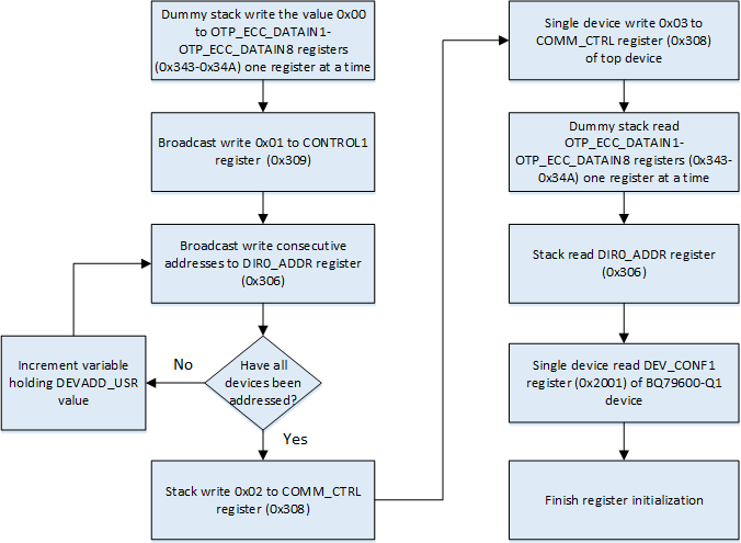
Dummy stack write 0x00 to registers OTP_ECC_DATAIN1 to OTP_ECC_DATAIN8 (register address 0x343 to 0x34A) on the BQ79616-Q1. This is a total of 8 stack writes (one for each register) to synchronize the DLLs used for reclocking the daisy chain interface.
Broadcast write 0x01 to register address 0x309 CONTROL1 to enable auto addressing.
Broadcast write consecutively to register address 0x306 DIR0_ADDR the values 0x00, 0x01, 0x02, and so forth to set the north communication device addresses.
Broadcast write 0x02 to register address 0x308 to set BQ79616-Q1 as stack devices.
Single device write 0x03 to register address 0x308 of top device (device 6 in this example) in order to set it as the top of the stack. Please note that this step is critical for broadcast reads to work properly!
Stack read registers OTP_ECC_DATAIN1 to OTP_ECC_DATAIN8 (register address 0x343 to 0x34A). This is a total of 8 stack reads (one for each register) intended to sync up internal DLL.
Stack read register address 0x306 to verify that all stack devices have been addressed correctly.
Single device read from the base BQ79600-Q1 device the register address 0x2001 and verify that the value is 0x14.
Proceed to register initialization.
 Figure 1-3 Auto-Addressing Flowchart