SLUUCE4 June 2021
5.1 Power Up
- Before beginning the power up test procedure, verify the connections with Figure 4-1.
- Enable supply #1, if the current on DMM1 is more than 0.25 mA and less than 0.8 mA, everything is set correctly.
- Enable function generator outputs channel-A and channel-B.
- The following conditions should be present:
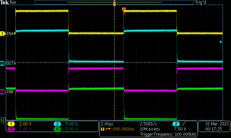
- Stable pulse output on channel-1 and channel-2 in the oscilloscope, refer to
- Frequency measurement should be 100 kHz, ±5 kHz or equal to the programmed function generator frequency
- DMM #1 should display around 4.6 mA, ±2 mA with the default load capacitance of 1.0 nF. For more information about operating current, see the UCC27624 DatasheetUCC27624 30-V 5-A dual channel low-side driver Data Sheet.
- Connect ENA_IN and ENB_IN test points to GND test point with jumpers. The pulse outputs on channel-1 and channel-2 will cease operation and the voltage level should be near ground.
 Figure 5-1 Example Input and Output
Waveforms