SLUUCE4 June 2021
4.3.5 Bench Setup Diagram
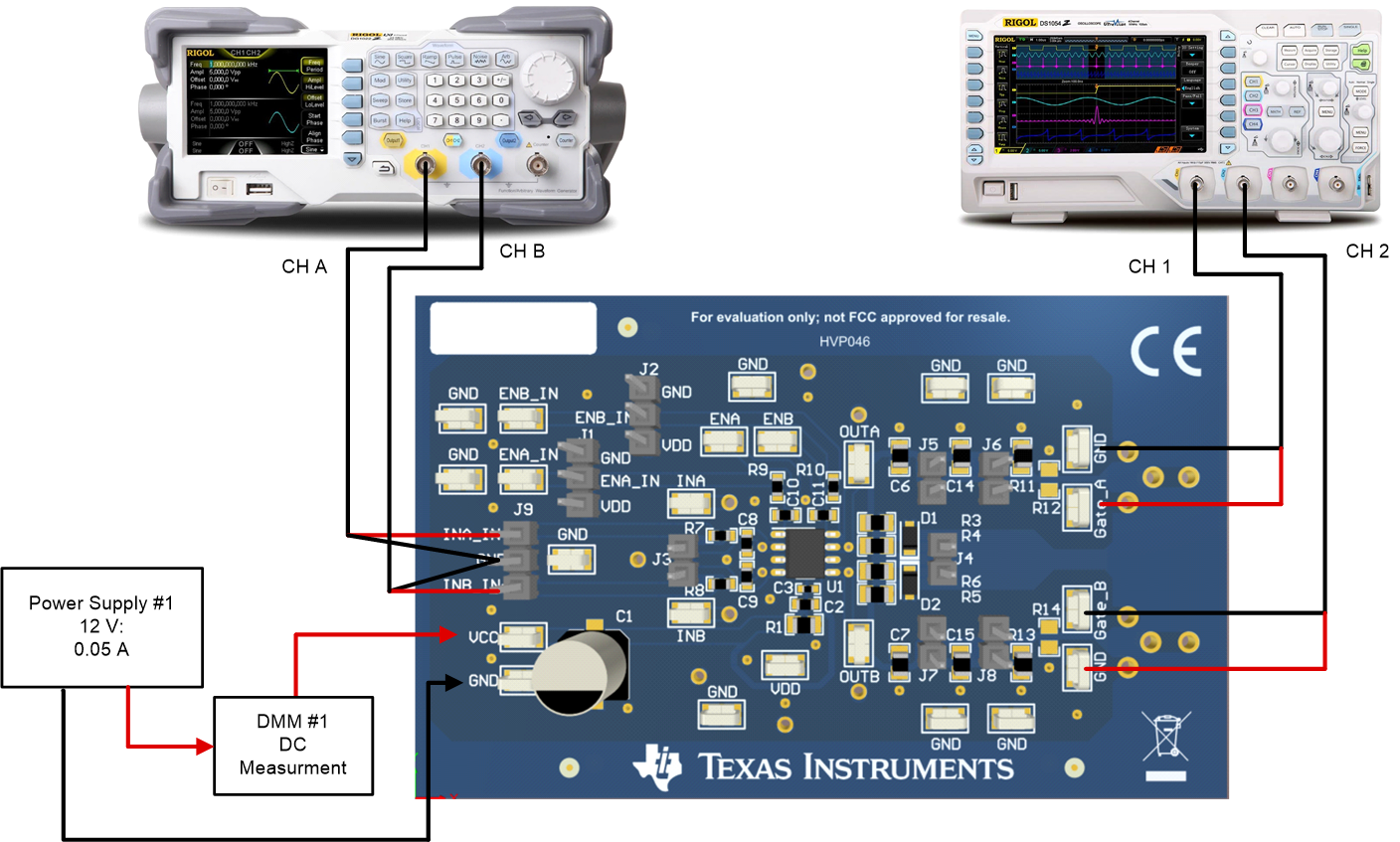
The bench setup diagram includes the function generator and oscilloscope connections.
Use the following connection procedure, refer to Figure 4-1.
- Make sure all the output of the function generator, voltage source are disabled before connection.
- Function generator Ch-A channel applied on INA_IN+, see in Figure 4-1.
- Function generator Ch-B channel applied on INB_IN-, see in Figure 4-1.
- Power supply #1: positive node connected to input of DMM #1 and DMM #1 output connected to test point marked as VCC, negative node of Power Supply #1 connected directly to test point marked as GND; see in Figure 4-1.
- Connect oscilloscope Ch-1 probes to test points marked as Gate_A, smaller measurement loop is preferred; see in Figure 4-1.
- Connect oscilloscope Ch-2 probes to test points marked as Gate_B, smaller measurement loop is preferred; see in Figure 4-1.
 Figure 4-1 Bench Setup Diagram and Configuration