SLUUCF8 March 2021 TPS53676
6.6 Bode plot
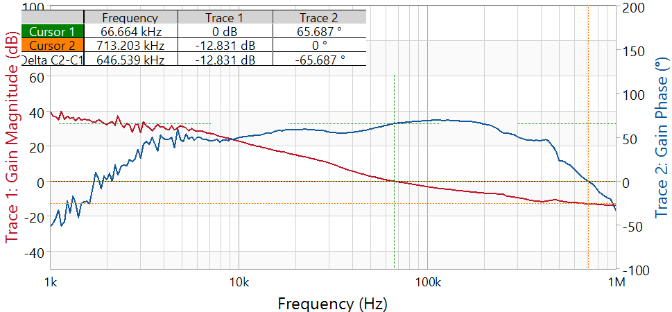
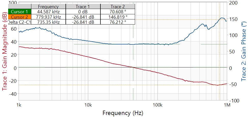
The EVM includes a provision to also perform a Bode plot to examine the control loop stability. To perform this test, a Spectrum analyzer is required. The resistor R10 (RAILA) or R13 (RAILB) must be replaced with an appropriate terminating resistor (usually 10 Ω or 20 Ω). The signal must be connected to parallel to R10 or R13. The loop gain is measured using the spectrum analyzer. Figure 6-14 and Figure 6-15 shows a measurement of the Bode plot made on this EVM for RAILA and RAILB.
 Figure 6-14 VOUTA Bode plot, Load current=50A
 Figure 6-15 VOUTA Bode plot, Load current=20A