SLUUCF8 March 2021 TPS53676
5 Test Equipment
Table 5-1 Required Test Equipment
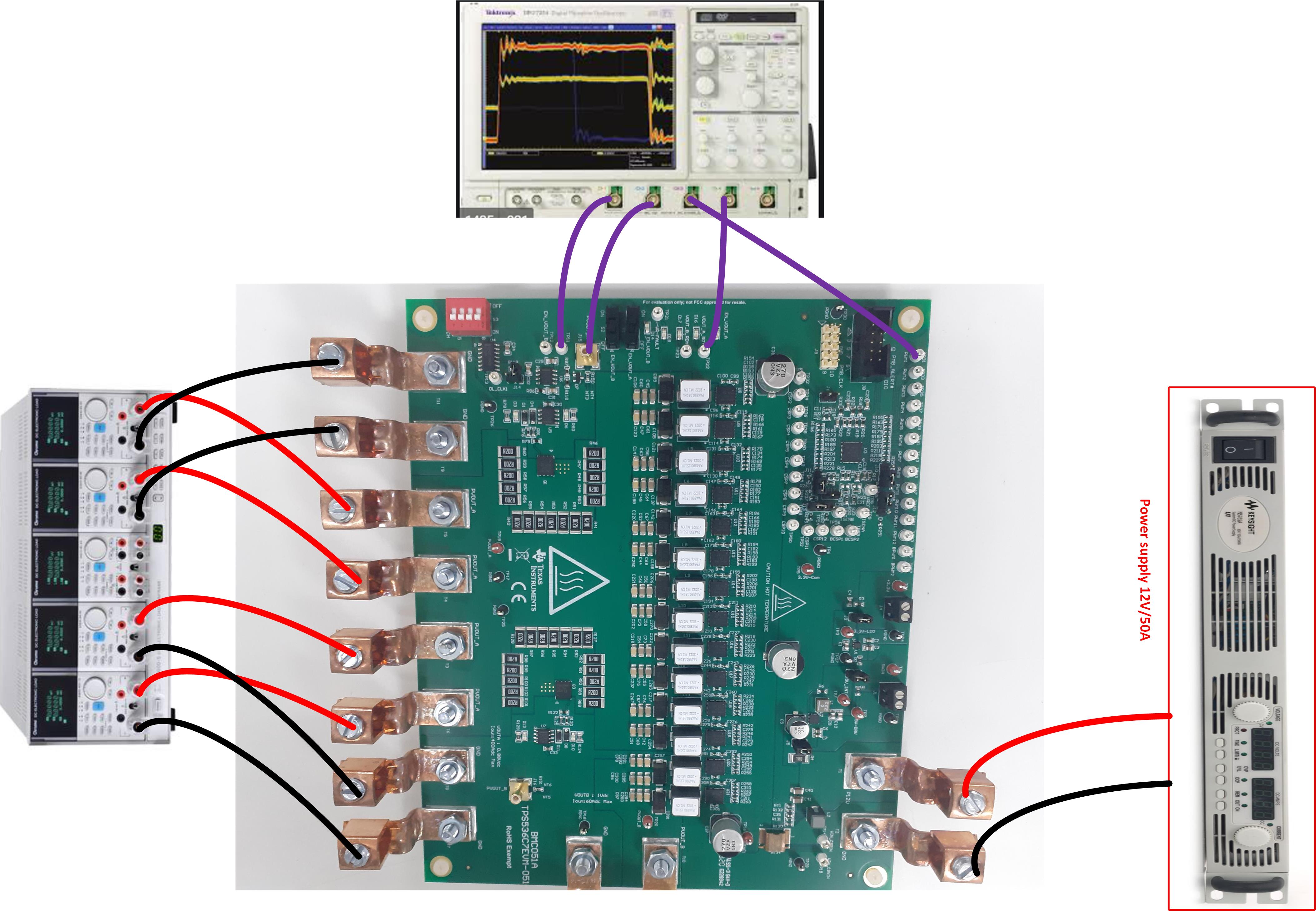
| Voltage sources | Only one DC input voltage source is needed (VIN). Choose a VIN input voltage source with a range between 0 V and 14 V and a variable DC source capable of supplying 40 A (dc). Connect VIN to terminals J6 and J7 as shown in Figure 5-1. For greater control during testing, remove jumpers from J2 and J4 to bypass the onboard 5-V power supply. Limit this external supply to 1 A (dc). |
| Multimeters | Recommended to use two separate multimeters, one meter to measure VIN and the other to measure VOUT. |
| Output Load | An electronic load is recommended for the test setup shown in Figure 5-1. To observe the Rail A at full load, ensure that the electronic load is capable of sinking 250 A at 0.88-V (Rail B, 50 A at 0.8 V) |
| Oscilloscope | Use an oscilloscope to measure output noise and ripple. Use a coaxial cable to measure output ripple across J15 (VOUTA) and J16 (VOUTB) |
| USB-to-GPIO Interface Adapter | A communications adapter is required between the EVM and the host computer. This EVM is designed to use the Texas Instruments USB-to-GPIO adapter connected to J12. To purchase this adapter, visit the TI USB-to_GPIO tool page |
| Fan | During prolonged operation at high load (More than 300 A), it is necessary to provide forced air cooling with a small fan aimed at the EVM. Maintain the temperature of the devices on the EVM under115°C |
 Figure 5-1 EVM Test Setup Showing the Power Supply, Load, and Oscilloscope Connections
Table 5-2 Recommended Wire Size
| VOLTAGE (V) | CONNECT | RECOMMENDED WIRE SIZE | MAXIMUM TOTAL WIRE LENGTH (FEET) | ||
|---|---|---|---|---|---|
| RETURN | INPUT | OUTPUT | |||
| 12 | VIN to T1, GND to T2 | 2 × AWG #8 | 2 | 2 | n/a |
| 5 (if J2 open) | 5VIN to J1 | 2 × AWG #18 | 2 | 2 | n/a |
| 0.88(RAILA) | Load+ to T3, T4, and T5, Load- to T7, T8, and T9 | 6 × AWG #4 | 3 | n/a | 3 |
| 1(RAILB) | Load+ to T10, Load- to T9 and T12 | 2 × AWG #8 | 1 | n/a | 1 |