SLUUCF8 March 2021 TPS53676
6.2 Shut down Test
Use the following procedure for the shutdown test:
RAILA:
Set the load current to 50 A.
Make sure all default jumpers(J1-J9) settings as shown in Table 4-3 .
Connect probes Enable (TP11), VOUTA (J15, BNC cable), PWM1 (TP31), and VOUT_A_RDY (TP22).
Set up the time / div on the oscilloscope to: 500 μs/div.
Set the trigger to channel 1 ‘Enable_A’ on the falling edge at about 1 V.
Turn on the power supply (with the voltage set to 12 V and the current limit set to 10 A).
Slide the enable switch ‘S1’ to the ON position and measure output voltage as 0.88V.
Turn-off the switch "S1" to OFF position.
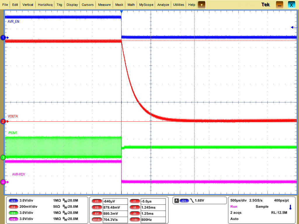
 Figure 6-3 VOUTA Enable OFF, Immediate-off
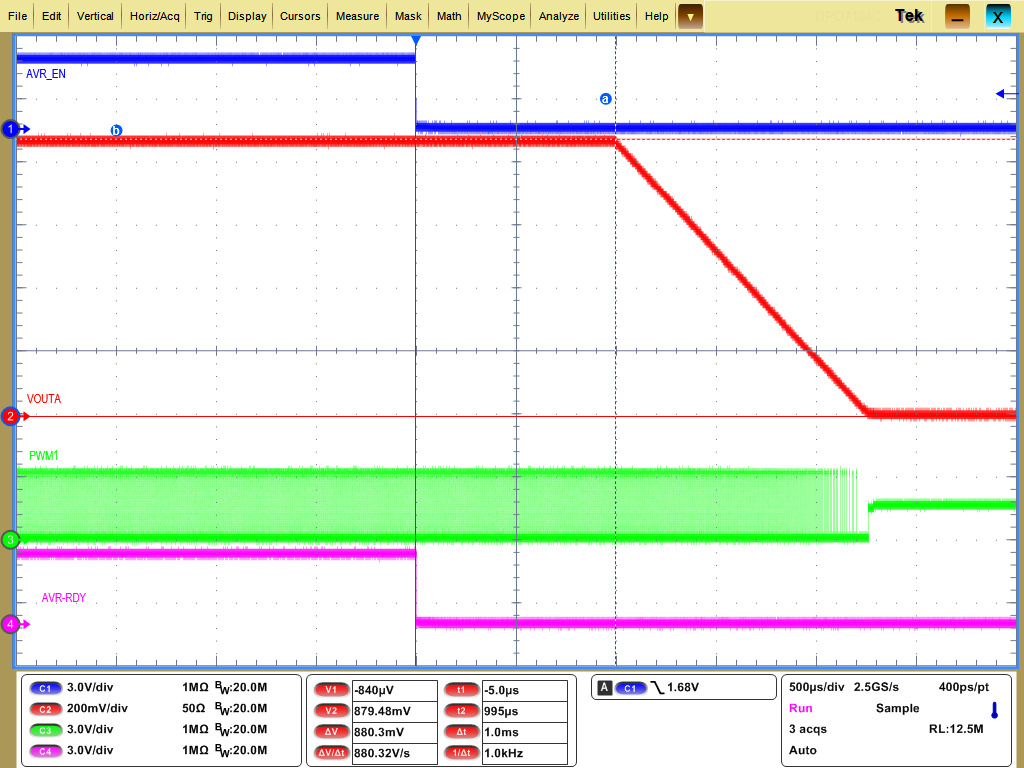
 Figure 6-4 VOUTA Enable OFF Soft-off with TOFF delay=1ms
RAILB:
Set the load current to 10 A.
Make sure all default jumpers (J1-J9) settings as shown in Table 4-3.
Connect probes Enable_B (TP12), VOUTB (J16, BNC cable), BPWM1 (TP55), and VOUT_B_RDY (TP23).
Set up the time / div on the oscilloscope to: 500 μs/div.
Set the trigger to channel 1 ‘Enable_B’ on the falling edge at about 0.8V.
Turn on the power supply (with the voltage set to 12 V and the current limit set to 5 A).
Slide the enable switch ‘S2’ to the ON position and measure output voltage as 0.8V.
Turn-off the switch "S2" to OFF position.
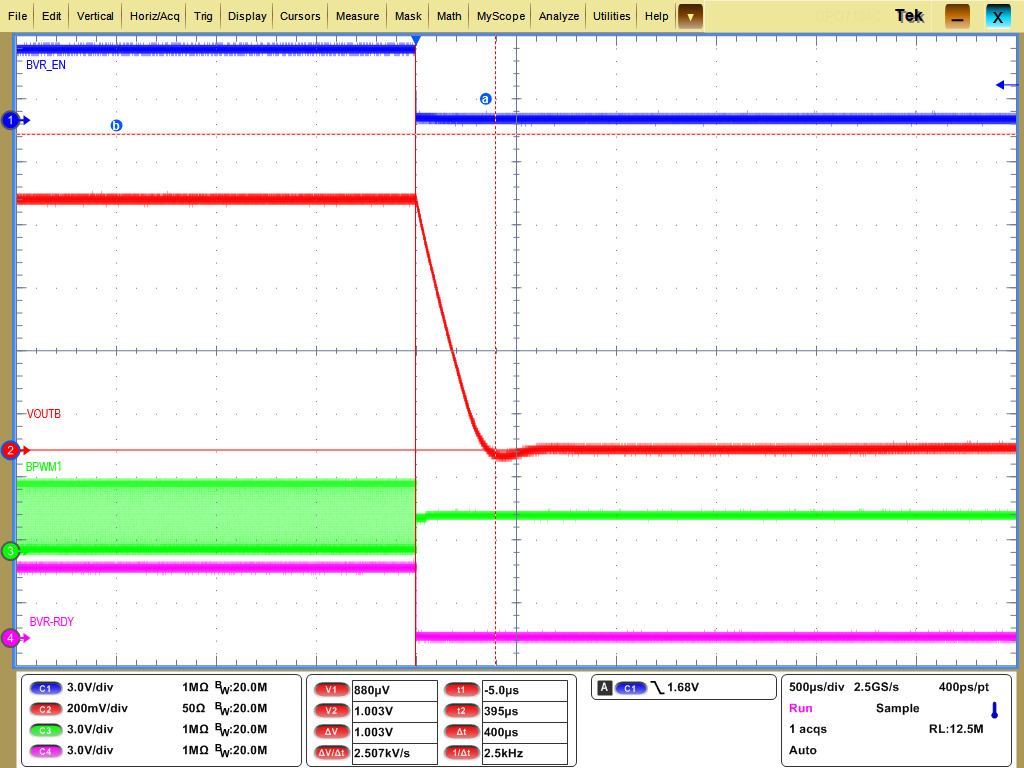
 Figure 6-5 VOUTB Enable OFF, Immediate-off
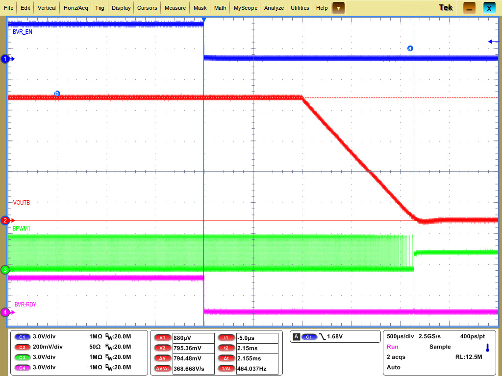
 Figure 6-6 VOUTB Enable OFF Soft-off with TOFF delay=1ms