SLUUCF8 March 2021 TPS53676
6.3 Steady-state Test
Use the following procedure for the steady-state test:
RAILA:
Set the load current to 50 A.
Make sure all default jumpers (J1 to J9) settings as shown in Table 4-3.
Connect probes VOUTA (J15, BNC cable), PWM1 (TP31), PWM2(TP32), and PWM3(TP33).
Add offset to VOUTA signal as 0.88V, and 4mV/div.
Set up the time / div on the oscilloscope to: 0.5 μs/div.
Turn on the power supply (with the voltage set to 12 V and the current limit set to 10 A).
Slide the enable switch ‘S1’ to the ON position and measure output voltage as 0.88V.
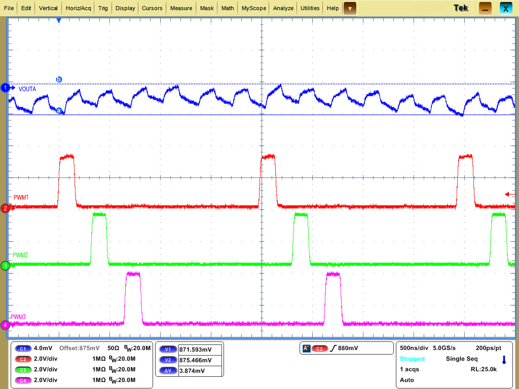
Measure output voltage ripple and phase interleaving.
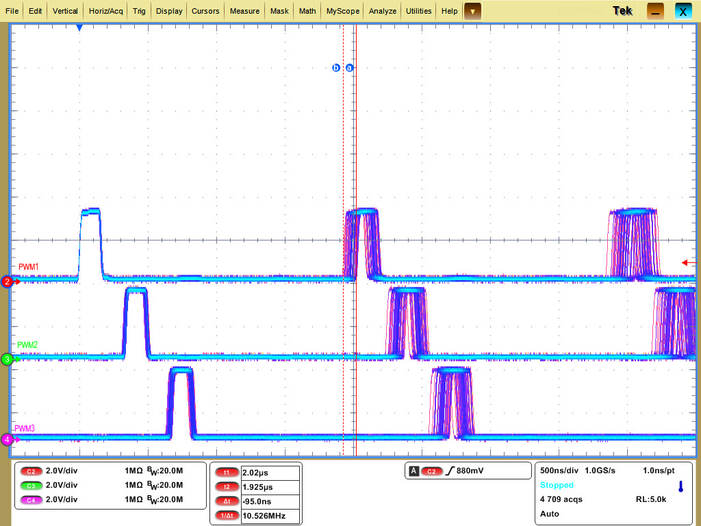
Jitter can be measured with set scope in "Fast acquisition mode".
 Figure 6-7 VOUTA Steady-state Output voltage Ripple
 Figure 6-8 VOUTA PWM Jitter
RAILB:
Set the load current to 10 A.
Make sure all default jumpers (J1 to J9) settings as shown in Table 4-3.
Connect probes VOUTB (J16, BNC cable), BPWM1 (TP31), BPWM2 (TP55), and PWM3(TP57) as shown.
Add offset to VOUTB signal as 0.8V, and 4mV/div.
Set up the time / div on the oscilloscope to: 1 μs/div.
Turn on the power supply (with the voltage set to 12 V and the current limit set to 10 A).
Slide the enable switch ‘S2’ to the ON position and measure output voltage as 0.8V.
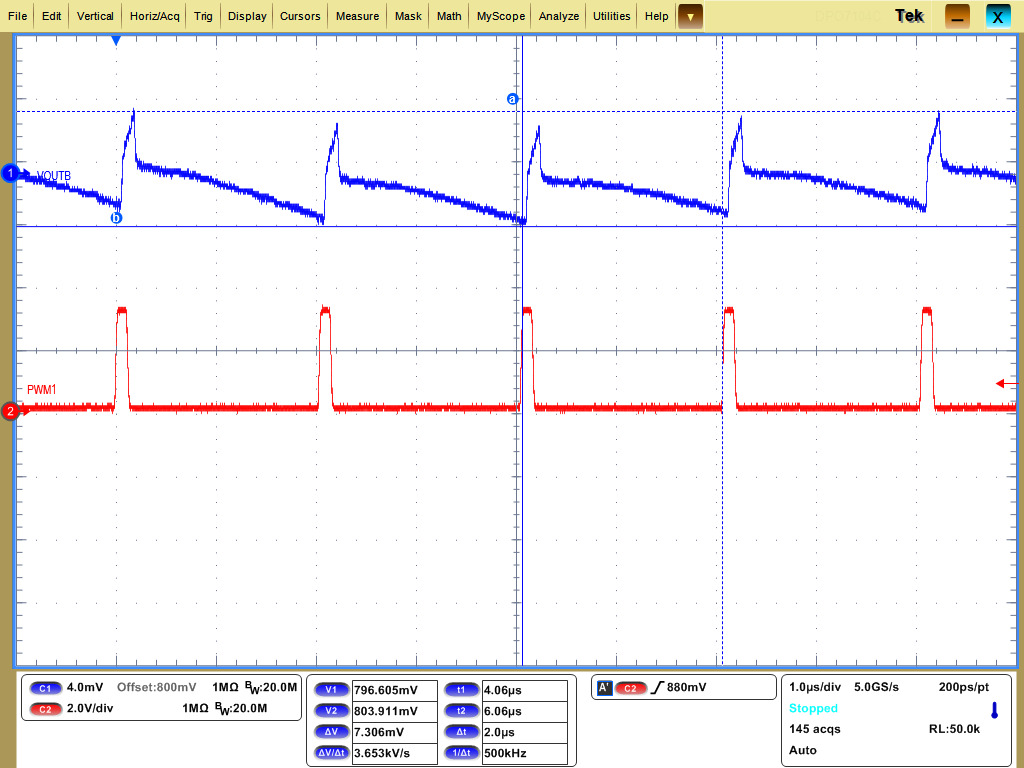
Measure output voltage ripple and phase interleaving.
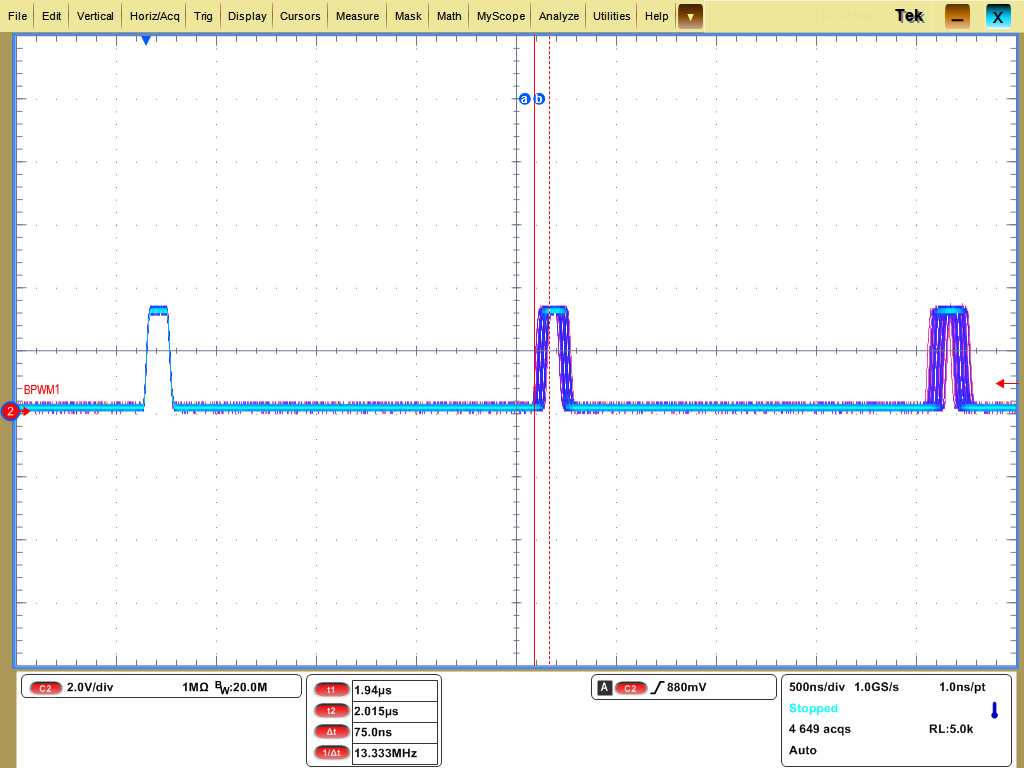
Jitter can be measured with set scope in "Fast acquisition mode".
 Figure 6-9 VOUTB Steady-state Output voltage Ripple
 Figure 6-10 VOUTB PWM jitter