SLUUCF8 March 2021 TPS53676
4 System Description
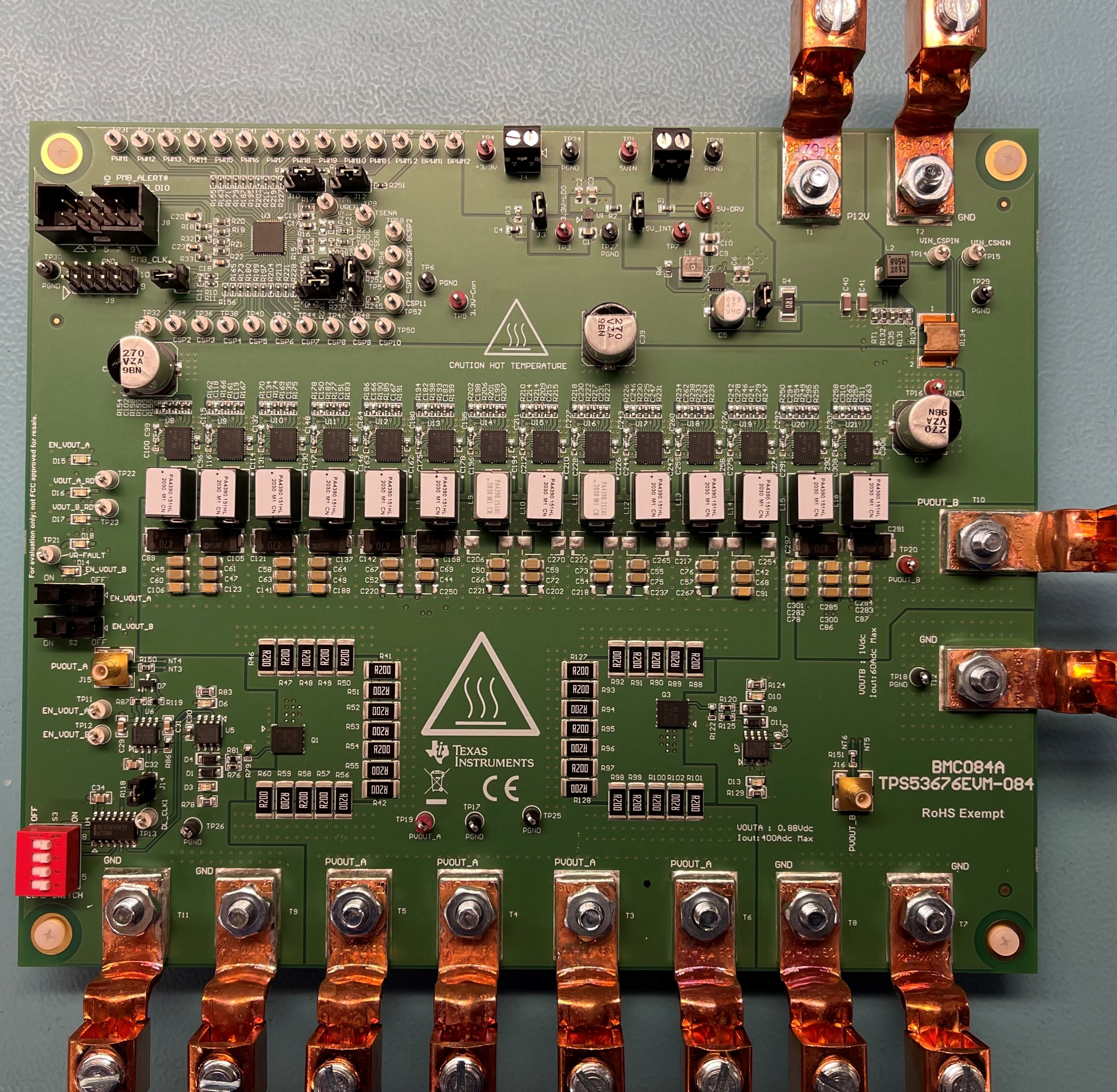
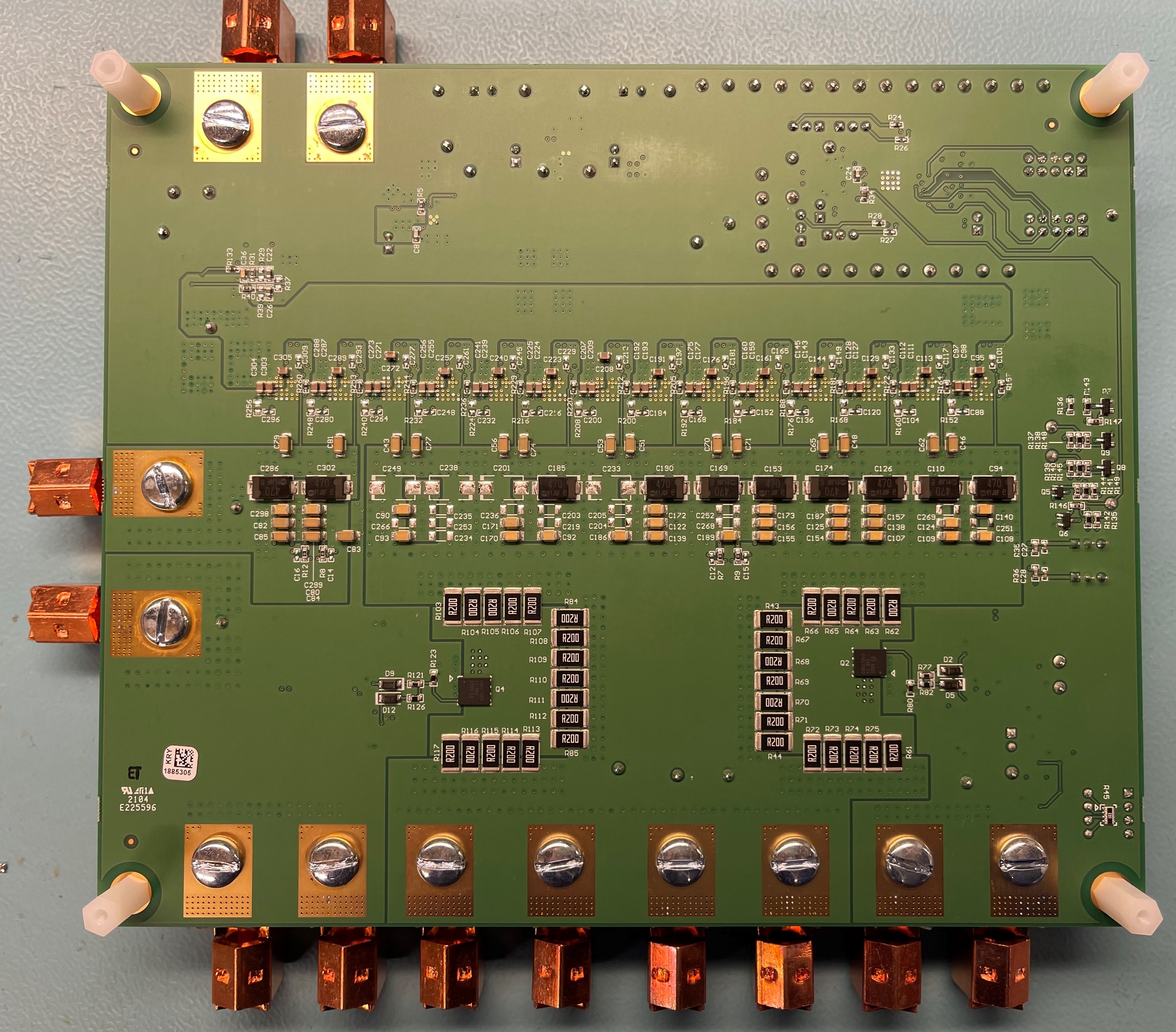
The TPS53676EVM-084 is a 7-phase comprehensive evaluation module (EVM) for CPU/ASIC core power rail applications using the TPS53676 controller. Figure 4-1 shows the top side of the EVM and Figure 4-2 shows the bottom side of the EVM. The EVM possesses several hooks for placing meters and probes by providing appropriate test points on various nodes.
The copper lugs T1 and T2 are the conversion input terminals to the step-down DC/DC converter. Input terminals are the point of connection of the input DC voltage.
With J5 closed, an on-board buck converter (TPS62133) generates the 5-V power stage VDD voltage. With J5 open, TPS62133 is disabled, and the 5-V supply must be applied to J1 externally. A 5-V to 3.3-V LDO (TLV75733) generates the 3.3-V controller bias voltage, and also supplies auxiliary circuits and LEDs on the EVM.
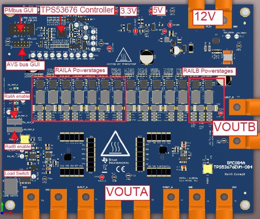
The output terminals T3, T4, T5, T6, T7, T8, T9, T10, and T11 are copper lugs providing a connection point for the high-current load. Figure 4-3 shows the location of all component details in the EVM. The setup is explained in detail in next section.
 Figure 4-1 EVM Top View
 Figure 4-2 EVM Bottom View
 Figure 4-3 EVM Options