SLUUCI9A January 2022 – December 2022 UCC28781
- Abstract
- Trademarks
- 1 Introduction
- 2 General Texas Instruments High Voltage Evaluation (TI HV EVM) User Safety Guidelines
- 3 Description of EVM
- 4 Electrical Performance Specifications of EVM
- 5 Schematic Diagram of EVM
- 6 Operating the EVM from a DC or an AC Source
- 7 Test Set-ups
-
8 Performance Data and Typical Characteristic Curves
- 8.1 Table of Efficiency Measurements with DC Input
- 8.2 Table of Efficiency Measurements with AC Input
- 8.3 Efficiency Graphs with DC Input Voltage (Typical Results)
- 8.4 Switching Frequencies in Various Operating Modes
- 8.5 Key Switching Waveforms and Operating Mode Load Current
- 8.6 Thermal Images at Full Load (15 V, 4.0 A) with DC and AC Inputs
- 9 Transformer Details
- 10EVM Assembly and Layout
- 11List of Materials
- 12Revision History
3 Description of EVM
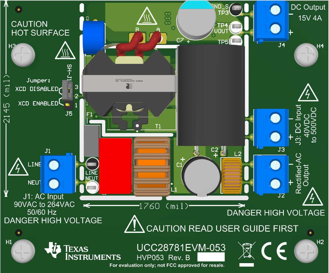
The UCC28781EVM-053 consists of a 4-layer printed circuit board (pcb) with through-hole components on the top side and surface-mount components on the bottom side. The actual conversion circuitry is contained within the break-away slots. Terminal blocks on the EVM for input and output connection are positioned outside the break-away slots to avoid being included in any power-density assessment. A jumper for enabling and disabling the X-capacitor discharge feature is also positioned outside the slots, since it is provided for evaluation purposes only.
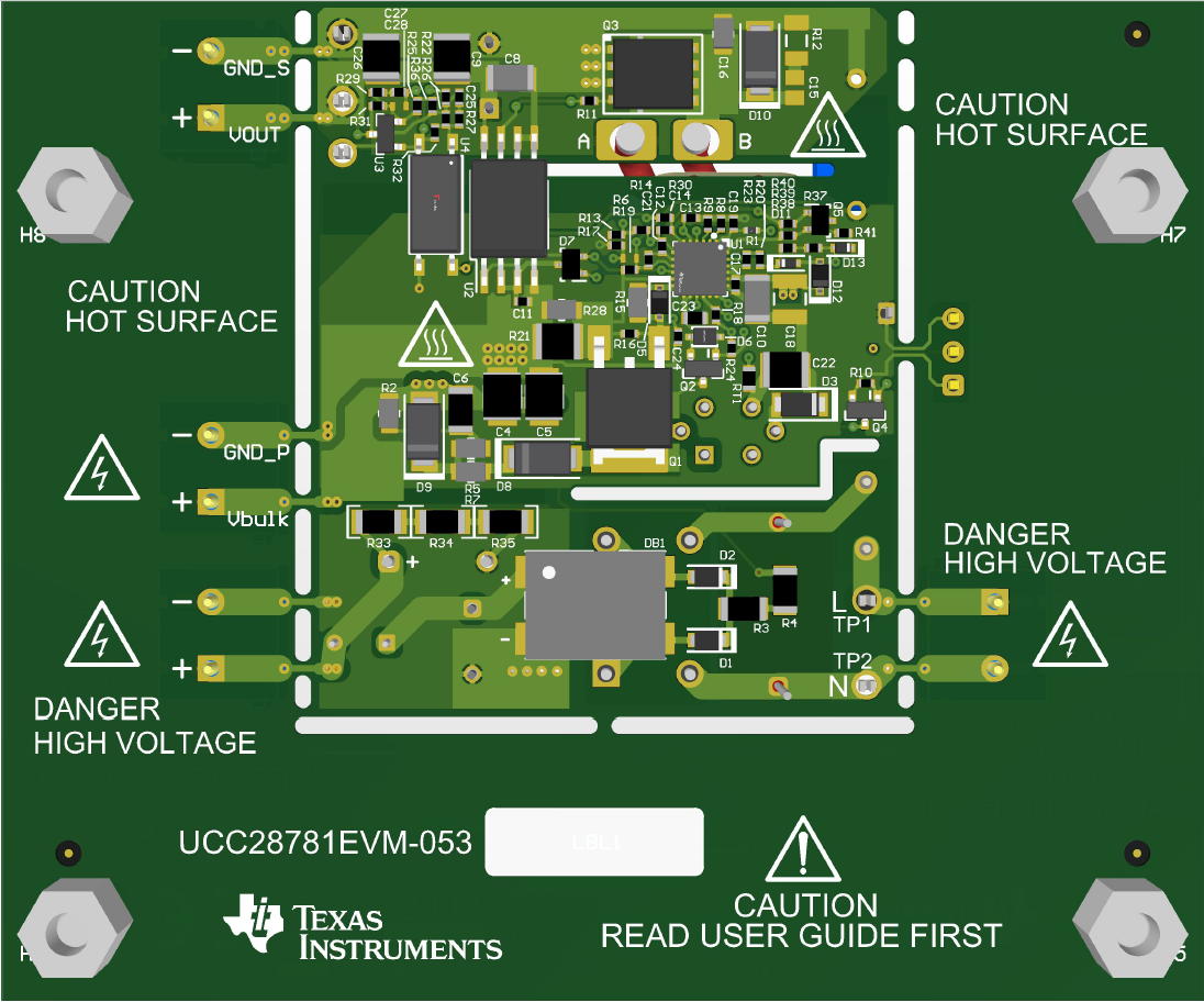
On the bottom side are resistors R33, R34, and R35 applied across the bulk capacitor C2 to provide rapid bleed-down of high voltage upon removal of AC input power, if the Rectified-AC Output was left unconnected to a load. Not normally used in a real design, their power loss is subtracted from measured input power.
The main devices used in this design are zero-voltage-switching flyback controller UCC28781-Q1 and isolated driver UCC5304 to the SR-FET. Please read this user's guide thoroughly before applying power to the EVM.
 Figure 3-1 UCC28781EVM-053 Top View
 Figure 3-2 UCC28781EVM-053 Bottom View